DSO26 User Manual
30
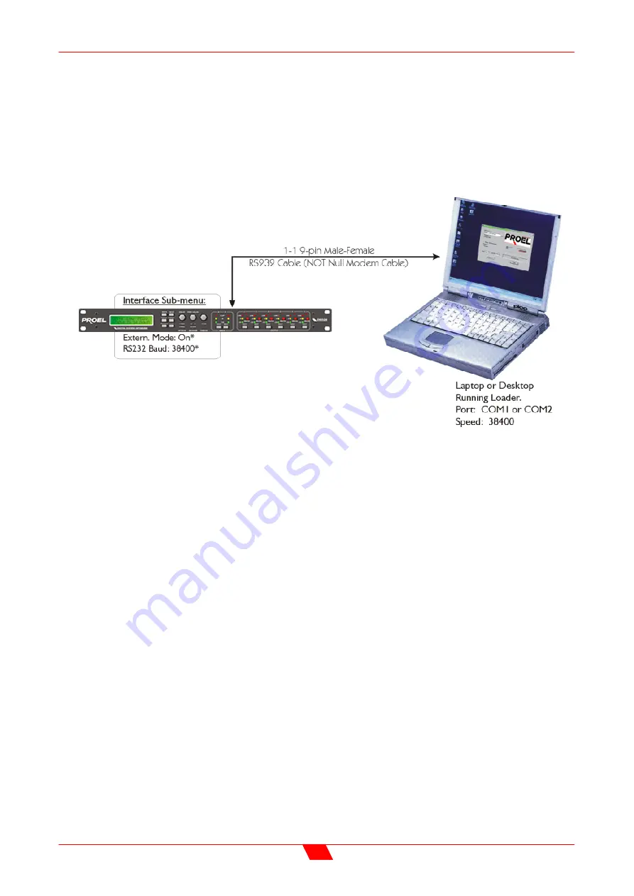
INTERFACE SUB-MENU
Interface Setup
If the interface is enabled, the option will become available to select the baud rate. This
must be set to match tat on the PC to be used for the program update. Typically, the set-
up would be as below.


