


www.prodem-attachments.com
EXTRAORDINARY MAINTENANCE
MAINTENANCE
39
Translated by the original
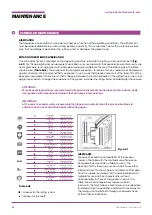
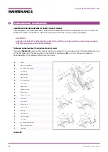
CLUTCH BLOCK
Definition:
The clutch block (
T
) is located on the frame of the attachment (
A
) above the center pin and it has the
function of keeping the movable jaw in line during cutting and avoiding scissoring. It has to do with an
adjustment slide block (
J
) that comes into slight contact with the sliding surface (
R
) of the movable jaw (
Q
).
Adjustment:
Carefully close the movable jaw until the adjustment slide block (
J
) of the clutch block is centered on the
sliding surface (
R
).
Remove the screw stop (
N
) and rotate the adjustment screw (
M
) clockwise that will push the adjustment
slide block against the sliding surface of the movable jaw.
Check that the play between the parts is between 0.1 and 0.2 mm and tighten the locking screws.
Do not tighten the adjustment slide block too much against the sliding surface so as not to lock the
movement of the movable jaw.
Replacement:
Unlock the screw stop (
N
) of the adjustment slide block (
J
) and loosen the adjustment screw (
M
).
Extract the adjustment slide block from its seat and replace it.
DANGER!
During the adjustment of the clutch block, it is necessary to activate the movable jaw, so make sure that
there is no one in the danger area or in points that the operator cannot see.
BLADES
DANGER!
During the adjustment of the blades, it is necessary to activate the movable jaw, so make sure that there
is no one in the danger area or in points that the operator cannot see.
IMPORTANT!
Turning the blades of the attachment increases the quality of the cut and extends the life of the blades.
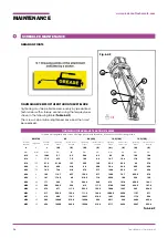
GUIDE BLADE
Definition:
The guide blade (
E
) is located on the front of the frame of the attachment (
A
) and has the function of guiding
the movable jaw (
Q
) during the cutting of the material.
Adjustment:
Partially close the movable jaw of the attachment so that the tip blade (
Z
) or the anti-wear plate (U),
depending on the model, located on the movable jaw (
Q
) meets the guide blade (
E
).
Slowly move the movable jaw (
Q
) and check the play between the tip blade (
Z
), or the anti-wear plate (
U
),
and the guide blade (
E
) in various positions. Make sure that it never exceeds 0.4 mm (it is initially adjusted
to 0.15 mm).
If the play is greater than required, restore the tolerances by inserting shims (
L
) behind the guide blade.
If excessive play remains despite the use of all the shims, it is possible to rotate the guide blade (
E
) for a
maximum of 4 times.
Содержание PDS 030R
Страница 46: ...www prodem attachments com NOTES...
Страница 47: ...www prodem attachments com NOTES...


