


5
1. The detector should be installed in a waterproof housing as close to the loop as possible.
2. The loop and feeder
should be made from insulated copper wire with a minimum cross-sectional area of
1.5mm
2
. The feeder should be twisted with at least 20 turns per metre. Joints in the wire are not
recommended and must be soldered and made waterproof. Faulty joints could lead to incorrect operation of
the detector. Feeders which may pick up electrical noise should use screened cable, with the screen earthed
at the detector.
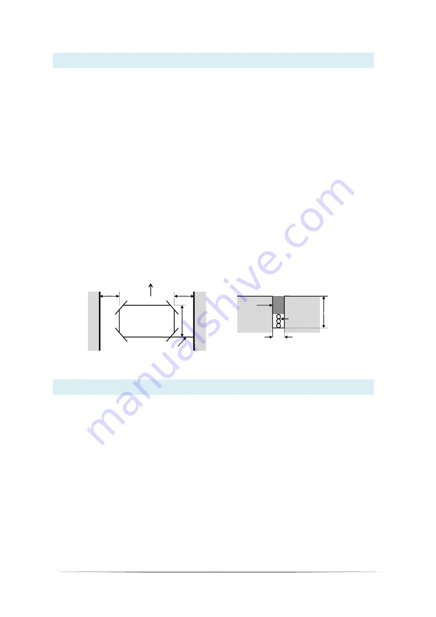
3. The loop should be either square or rectangular in shape with a minimum distance of 1 metre between
opposite sides. Normally 3 turns of wire are used in the loop. Large loops with a circumference of greater than
10 metres should use 2 turns while small loops with a circumference of less than 6 metres should use 4 turns.
When two loops are used in close proximity to each other it is recommended that 3 turns are used in one and
4 turns in the other to prevent cross-talk.
4. Cross-talk is a term used to describe the interference between two adjacent loops. To avoid incorrect
operation of the detector, the loops should be at least 2 metres apart and on different frequency settings.
5. For loop installation, slots should be cut in the road using a masonry cutting tool. A 45
o
cut should be made
across the corners to prevent damage to the wire on the corners. The slot should be about 4mm wide and
30mm to 50mm deep. Remember to extend the slot from one of the corners to the road-side to accommodate
the feeder.
6. Best results are obtained when a single length of wire is used with no joints. This may be achieved by running
the wire from the detector to the loop, around the loop for 3 turns and then back to the detector. The feeder
portion of the wire is then twisted. Remember that twisting the feeder will shorten its length, so ensure a long
enough feeder wire is used.
7. After the loop and feeder wires have been placed in the slot, the slot is filled with epoxy compound or bitumen
filler.
1. Connect the wiring according to the pin-out on the side label of the detector.
1.1
Connect the power supply to the terminals 1 & 2.
1.2
Connect the loop to the terminals 7 & 8.
1.3
Connect the relay outputs as required. The relays are fail safe and the normally open/normally closed
contacts are indicated with the detector switched on and tuned to the loop, with no vehicle on the loop.
2. The next step is setting the 4 way switch on the front of the unit.
2.1
Set up the desired sensitivity on switches 2, 3 and 4. The settings can be seen on the side label. For
normal operation of 0.02% switch off switches 2, 3 and 4.
2.2
The frequency switch 1 is used to change the loop frequency. If the loop detector is experiencing
interference from an adjacent detector ( crosstalk) or from another source, the problem can be
eliminated by switching this switch on. For normal operation this switch can be off.
To conclude the switch setting, all the switches can normally be left in the off position. ie: all of the switches are
toward the outside edge of the detector.
LD160 Configuration
Loop Installation Guide
300mm
300mm
1M
ROAD
EDGE
45
O
CROSSCUT
FEEDER
TRAFFIC DIRECTION
4mm
ROAD SURFACE
30-50 mm
SLOT
SEALANT
WIRES


