background image

2 3

   Q  SERIES  LOG  SET

INSTALLATION  INSTRUCTIONS

Содержание QL300RYLA

Страница 1: ...of this or any other appliance WHAT TO DO IF YOU SMELL GAS Do not try to light any appliance Do not touch any electrical switch do not use any phone in your building Immediately call your gas supplier from a neighbor s phone Follow the gas supplier s instructions If you cannot reach your gas supplier call the fire department Installation and service must be performed by a qualified installer servi...

Страница 2: ...n warnings 3 Air for conbustion Ventilation 5 Installation 7 Operation Heater 11 Cleaning and Maintenance 13 Specification 15 Troubleshooting 16 Parts Breakdown Parts List 18 Log Placing Instructions 22 Table of Contents ...

Страница 3: ...u must operate this heater with the heater screen in place Make sure the heater screen is in place before running heater Keep the appliance area clear and free from combustible materials gasoline and other flammable vapors and liquids 1 This appliance is only for use with the type of gas indicated on the rating plate This appliance is not convertible for use with other gases 2 Do not place Propane...

Страница 4: ...s damaged promptly inform dealer where you bought stove PRODUCT FEATURES SAFETY PILOT This heater has a pilot with an Oxygen Depletion Sensing ODS safety shutoff system The ODS pilot is a required feature for vent free room heaters The ODS pilot shuts off the heater if there is not enough fresh air PRODUCT IDENTIFICATION Figure1 Vent Free LP NG Gas Stove Remote control SYSTEM This fireplace has a ...

Страница 5: ...R LOCATION Determining if You Have a Confined or Unconfined Space Use this worksheet to determine if you have a confined or unconfined space Space Includes the room in which you will install heater plus any adjoining rooms with doorless passageways or ventilation grills between the rooms 1 Determine the volume of the space length width height Length Width Height cu ft volume of space Example Space...

Страница 6: ...nfined Figure 2 Ventilation Air from Inside Building Example Gas water heater 30 000 Btu Hr Vent free heater 26 000 Btu Hr Total 56 000 Btu Hr WARNING If the area in which the heater may be operated is smaller than that defined as an unconfined space or if the building is of unusually tight construction provide adequate combustion and ventilation air by one of the methods described in the National...

Страница 7: ...Follow all local codes WARNING Never install the heater in a bedroom or bathroom in a recreational vehicle where curtains furniture clothing or other flammable objects are less than 42 inches from the front top or sides of the heater in high traffic areas in windy or drafty areas WARNING Maintain the minimum clearances If you can provide greater clearances from floor ceiling and adjoining side and...

Страница 8: ...re installing heater make sure you have the items listed below piping check local codes sealant resistant to propane LP gas equipment shutoff valve test gauge connection sediment trap tee joint pipe wrench flexible gas hose check local codes A CSA design certified equipment shutoff valve with 1 8 NPT tap is an acceptable alternative to test gauge connection Purchase the optional CSA design certifi...

Страница 9: ...s not installed or is installed incorrectly heater may not run properly CAUTION Avoid damage to regulator Hold gas regulator with wrench when connecting into gas piping and or fittings WARNING Never use an open flame to check for a leak Apply a mixture of liquid soap and water to all joints Bubbles forming show a leak Correct all leaks at once CAUTION Make sure external regulator has been installe...

Страница 10: ...ck to see if flames contact any log If so reposition logs according to the log installation instructions in this manual Flames contacting logs will create soot It is very important to install the logs exactly as instructed Do not modify logs Only use logs supplied with heater Place log set on grate to fit as illustrated in Figure 10 Make sure log sits flat on firebox floor see Figure 10 IMPORTANT ...

Страница 11: ...PERATING INSTRUTIONOF REMOTE CONTROLLEDBUNER LIGHTING INSTRUCTIONS 1 STOP Read the safety information page 2 2 Make sure equipment shutoff valve is fully open Figure 12 1 Emergency Button location C Use only your hand to push in control knob Never use tools If the the appli ance could not operate don t try to repair it Call a qualified service technician or gas supplier Forced or at tempted re pai...

Страница 12: ... step 2 Point directly the remote transmitter to the burner Press IGN OFF button the electric spark starts igniting the pilot and operation light green on the front will be lit Wait five 5 minutes to clear out any air If you smell gas STOP Please check the gas connection There are three selections AUTO MAN and OFF a auto select of main burner Press BURNER button the flame is on AUTO select Press ø...

Страница 13: ...are three selections AUTO MAN and OFF When pushing the FAN button on the AUTO select the fan will be controlled by the thermostat on the fan blower unit On the MAN select the fan will be kept in operation To stop the operation push the FAN button to OFF select See Fig17 CAUTION You must keep c o n t r o l a r e a s b u r n e r a n d circulating air passageways of heater clean Inspect these areas o...

Страница 14: ...cuum cleaner nozzle 5 Blow air into the primary air holes on the injector holder 6 In case any large clumps of dust have now been pushed into the burner repeat steps 3 and 4 Clean the pilot assembly also A yellow tip on the pilot flame indicates dust and dirt in the pilot assembly There is a small pilot air inlet hole about two inches from where the pilot flame comes out of the pilot assembly see ...

Страница 15: ... of input adjustment FLEXILBE HOSE Flexibe gas hose is used for connect ing the heater to gas supply the flex hose must approved by CSA from your local dealer or Parts Central This part is not currently available from PRO COM EQUIPMENT SHUTOFFVALVE Equipment shutoff valve with 1 8 NPT tap Purchase date Usually we will ask you to return the defective part to the factory Warranty card PARTS NOT UNDE...

Страница 16: ...n transmitter or battery isn t correctly assembly 1 Check the electric power 2 Place or replace the battery 1 Thermocouple connection loose at control board 2 Pilot flame not touching thermcouple which allows thermo couple to cool causing pilot flame to go out This problem could be caused by one or both of the following A Low gas pressure B Dirty or partially clogged ODS pilot 3 Thermocouple damag...

Страница 17: ...gulator defective 1 Problem will stop after a few hours of operation 2 Check burner for dirt and debris If found clean burner see Cleaning and Maintenance page 13 3 Replace gas regulator Dark residue on logs or inside of fireplace 1 Improper log placement 2 Air holes at burner inlet blocked 3 Burner flame holes blocked 1 Properly locate logs see installing logs page 26 2 Clean out air holes at bur...

Страница 18: ...1 8 ILLUSTRATED PARTS BREAKDOWN QL300RYLA QN300RYLA QL300RYLA W QN300RYLA W ...

Страница 19: ...1 9 PARTS LIST QL300RYLA QN300RYLA QL300RYLA W QN300RYLA W ...

Страница 20: ...2 0 ILLUSTRATED PARTS BREAKDOWN QL300RYLA QN300RYLA QL300RYLA W QN300RYLA W ...

Страница 21: ...2 1 PARTS LIST QL300RYLA QN300RYLA QL300RYLA W QN300RYLA W ...

Страница 22: ...s to put log sets in place to the gas stove indoor vent free NOTICE THE CORRECT POSITION OF THE LOGS SHOULD NOT IM PINGE ON THE FLAME THE LOG S PACKAGE IS LOCATED INSIDE THE UNIT THEN REMOVE SCREEN AND TAKE OUT THE LOG S PACKAGE FIRST REMOVE TWO TOP SCREWS FROM SCREEN BOTTOM PANEL ...

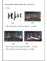
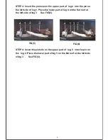
Страница 23: ...2 3 Q SERIES LOG SET INSTALLATION INSTRUCTIONS ...

Страница 24: ...he log 2 on the right rear angle iron see FIG 3 STEP 3 Install the log 3 on the front angle iron See FIG 4 1 INSTALLATION INSTRUCTIONS FOR LOG SETS 1 All logs FIG 1 FIG 2 STEP 1 Install the log 1 on the left rear angle iron see FIG 2 ...

Страница 25: ...in on the left side of log 1 Place the lower part of log 4 on the flat roof at the left side of log 3 See FIG 5 STEP 4 Insert the pinhole on the upper part of log 5 into the pin on the log 2 Place the lower part of log 5 on the flat roof at the left side of log 3 See FIG 6 FIG 6 ...

Отзывы: