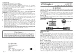
O UTP UTS
UH F
INP UT
V HF
INP UT
1
2
3
4
PRO ception
TV
IN
pr oSAT 1EYE
Page 3
Page 2
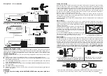
Outlet plates
The TV connection in the remote room may use a wall outlet plate. Note that some types of
existing outlet plate, particularly the isolated types illustrated, are not compatible with the proSAT1EYE
system and will need to be replaced. Replacement plates are readily available from electrical or TV
retailers, or DIY stores.
The replacement should be a single non-isolated outlet plate.
Alternatively, non-isolated dual TV/radio outlets are also
compatible, provided that they have DC continuity to the
the TV connector - check this point with your supplier before
purchasing replacements.
Use of an incompatible outlet plate will prevent power from
reaching the coupler (red LED indicator not lit) and this in
turn will stop the remote control function working.
Coaxial plugs
Correct fitting of the coaxial plugs used to make connection to the components is crucial to obtaining
the best results from your system. Achieving sound braid and centre connections is important. Any
good quality type of coaxial plug is suitable, but note that fitting some types invoves a soldering
operation. The sequence of diagrams below illustrates how to fit the most common type of plug
correctly (this type requires the centre connection to be soldered). Other plugs may vary and some
solderless types use a screw clamp connection or spring centre contact. Any specific fitting instructions
supplied with your plugs should take precedence over the diagrams here.
Failure to solder the
centre connection where necessary may result in intermittent or unreliable remote control
operation.
Configure the Digibox or PVR
The purpose of this step is to configure the Digibox or PVR to supply 9 volt power to the remote
receiver eye. Normally this is only required for the direct extension cable system (Wiring Plan 1).
This step is not required if the signal feed to the remote room arrives via a mains-powered
amplifier (Wiring Plan 2).
This step should be carried out in the room containing the Digibox or PVR (usually at the main TV
location).
n
Switch-on the main TV and the Digibox or PVR, and select a digital satellite channel.
n
Using the Sky* handset, select the services menu by pressing the SERVICES button and choose
the SYSTEM SET-UP option (4).
n
From the SYSTEM SET-UP option, press 0 then 1, then press the SELECT button on the handset
for the INSTALLER SET-UP menu.
n
Choose the RF OUTLETS option (4) and select SECOND OUTLET POWER SUPPLY. Select ON and
then save settings.
n
Press BACK UP to return to TV Viewing.
n
Check on your main TV that you can see all your terrestrial TV channels and the digital channels
that you subscribe to.
WARNING:
Changing any other settings in the INSTALLER SET-UP menu may cause problems.
Wiring Plan 2 with distribution system
Wiring Plan 1 direct extension
receiver eye
a) First place the cap over cable. Strip away cable outer
sheath. Take great care not to cut through the braid
wires. Strip away insulation to reveal inner conductor.
b) Bundle the braid wires together
and slide the clamp over cable.
c) Dress the braid wires evenly over clamp. Push cable and clamp into connector body. Solder the
inner conductor to the contact pin as shown. Screw cap and outer body securely together.
trim and solder end of inner conductor to inner contact here
outer body
clamp
Cap
inner conductor
connector body
16 mm
22 mm
coupler
flylead
second TV
main TV
Sky* digibox
VCR
RF OUT-2
RF OUT-1
receiver eye
coupler
flylead
second TV
main TV
distribution amplifier
to additional TVs
RF OUT-2
Sky* digibox
VCR
RF OUT-1
Old isolated outlet plates -
not compatible with proSAT1EYE
TV
FM
PRO ception
TV
IN
pr oSAT 1EYE
Tuning and testing
Before testing remote control operation ensure that all remote room TV(s) have a channel setting
tuned-in to the output channel from the Digibox or PVR. If the extension cable or distribution system
is newly installed this tuning will need to be carried out for the first time. Select a digital satellite
channel on the Digibox or PVR and tune an unused channel setting on each remote room TV into
the satellite programme. (By default the output from the Sky* equipment is found on UHF channel
68, but this can be changed if necessary.) Refer to your TV manual or manufacturers help line or
Web site if you are unsure how to retune your TV.
Now check that the red LED indictor on the coupler is alight. This confirms that the coupler and
receiver eye are receiving power from the Digibox, PVR or amplifier. If this LED is not lit refer to the
troubleshooting instructions on page 4.
Finally test remote control operation by taking the Sky* remote control handset to the remote room
and operating it.


