


ComBricks User Manual v6.4.0 | January 18| © PROCENTEC
84/219
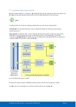
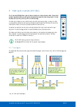
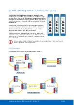
7.2
Channel structure
Every Channel is electrically isolated and internally connected to one of the transparent PROFIBUS networks on
the backplane (see
).
The shielding of the PROFIBUS cable can be directly grounded or indirectly grounded (see
Paragraph 7.4
).
The termination is switchable and powered by the repeater module. A LED on the front of the module or in the
web server diagnostics indicate the status of the termination switch.
For the old models: When the termination is switched ON, the OUT connector of the specific
channel is disconnected. If it is activated on Channel 1, the DB9 connector is NOT disconnected. In
that case, check for possible termination errors. An extra termination on the connected plug could
jeopardize the communication on the segment. See paragraph 3.11 for examples.
Fig. 51 - Channel structure of the repeater modules
Содержание ComBricks
Страница 1: ...User Manual ...
Страница 132: ...ComBricks User Manual v6 4 0 January 18 PROCENTEC 132 219 ...
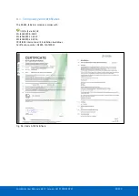
Страница 213: ...ComBricks User Manual v6 4 0 January 18 PROCENTEC 213 219 44 Certificates ...
Страница 214: ...ComBricks User Manual v6 4 0 January 18 PROCENTEC 214 219 ...
Страница 215: ...ComBricks User Manual v6 4 0 January 18 PROCENTEC 215 219 ...
Страница 216: ...ComBricks User Manual v6 4 0 January 18 PROCENTEC 216 219 ...
Страница 217: ...ComBricks User Manual v6 4 0 January 18 PROCENTEC 217 219 45 Notes ...
Страница 218: ...ComBricks User Manual v6 4 0 January 18 PROCENTEC 218 219 ...