background image

Description 


15 / 21 


4.


Description 

This chapter provides general information about the machine. This chapter is intended for the 
owner, the operator and the maintainer of the machine. 

4.1.


General 

This user manual includes an appendix with an exploded view drawing. This drawing includes a 
parts list containing the name of each part. 

4.2.


Construction of the machine 

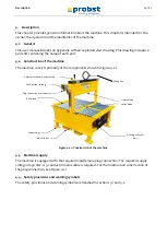
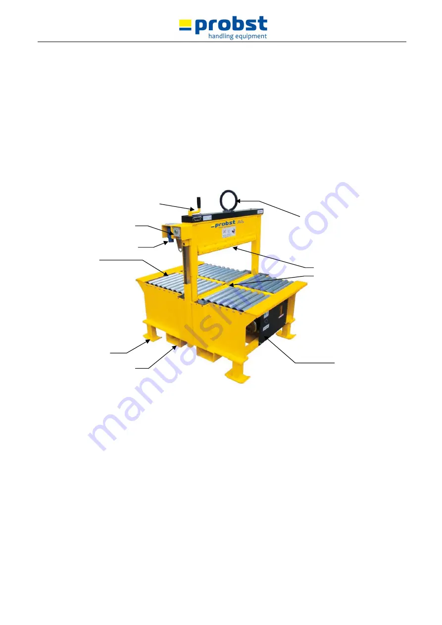
The machine consists primarily of the components shown in Figure 4.2-1. 


Figure 4.2-1: Construction of the machine 

4.3.


Electrical supply 

The machine is equipped with the required male/female plug connection. The required supply 
voltage is 230 VAC. A 3-conductor mains cable is required. For the location and construction of 
the plug connection, see Figure 4.2-1 

4.4.


Safety provisions and warning symbols 

The safety provisions and warning symbols are handled in sections 3.1 and 3.2. 


Lifting eye 

Adjustment handle, upper blade 

Plug connection, mains power 

Support legs 

Roller bed 

Fork lift tubes 

Upper blade 

Lower blade 

Housing hydraulic 

unit 

Push button, cutting 

Содержание AL-90

Страница 1: ...51200054 V1 DEȀ Bedienungsanleitung Hydraulischer Platten und Verbundsteintrenner AL 90 NSH 40 ...

Страница 2: ...sanleitung in Landessprache falls die Übersetzung nicht durch den Händler Importeur organisiert werden kann Please note that the product may not be used put into operation without these operating instructions in the national language If you did not receive operating instructions in your national language with the delivery of the product please contact us In countries of the EU EFTA we will send th...

Страница 3: ......

Страница 4: ...51200054 V1 DE Bedienungsanleitung Hydraulischer Platten und Verbundsteintrenner Typ AL 90 NSH 40 ...

Страница 5: ...12 3 2 Gebotsschilder auf der Maschine 13 3 3 Allgemeine Sicherheitsvorschriften 14 3 4 Bediener 14 3 5 Wartungstechniker 14 3 6 Aufstellung der Maschine 15 3 7 Geräuschentwicklung der Maschine 15 3 8 Wartung der Maschine 15 3 9 Zusammenfassung der Sicherheitsvorschriften 15 4 Beschreibung 16 4 1 Allgemeines 16 4 2 Aufbau der Maschine 16 4 3 Stromversorgung 16 4 4 Sicherheitsvorrichtungen und Gebo...

Страница 6: ...ser 8 Abbildung 2 4 3 Dreieckige Messer verteilt 8 Abbildung 2 4 4 Basalt Messer verteilt 9 Abbildung 2 4 5 Basalt Messer in der Mitte 9 Abbildung 2 4 6 Ersetzen von Klingen 9 Abbildung 2 4 7 Maximale Formabweichung vom Stein 10 Abbildung 2 4 8 Keine unregelmäßigen Steine 10 Abbildung 3 2 1 Gebotsschilder auf der Maschine 13 Abbildung 4 2 1 Aufbau der Maschine 16 Abbildung 6 3 1 Piktogramm Steine ...

Страница 7: ...etz zu trennen Vorsicht vor beweglichen scharfen oder herausragenden Teilen Diese können Verletzungen verursachen Während des Schneidens immer einen Sicherheitsabstand einhalten 1 3 Zielgruppen pro Kapitel Diese Anleitung dient zur Information folgender Personen bzw Abteilungen Eigentümer Bediener Wartungstechniker Unter dem Titel jedes Kapitels ist angegeben an welche der oben genannten Zielgrupp...

Страница 8: ...nschäden 1 5 Nachbestellen der Bedienungsanleitung Zusätzliche Exemplare der Bedienungsanleitung sind bei Probst erhältlich Geben Sie bei Ihrer Bestellung die Dokumentnummer und die Anzahl der gewünschten Exemplare an Die Dokumentnummer finden Sie im Fußtext 1 6 Fehler in der Bedienungsanleitung Diese Bedienungsanleitung wurde mit der größtmöglichen Sorgfalt verfasst Sollten Sie dennoch Fehler ode...

Страница 9: ... Fachkräften vom Technischen Dienst ausgeführt werden Die in Abschnitt 1 3 angegebenen Kapitel sind vom Wartungstechniker sorgfältig durchzulesen 2 2 Hersteller Der Hersteller der Maschine ist Probst GmbH Gottlieb Daimler Straße 6 D 71729 Erdmannhausen info probst handling de www probst handling de 2 3 Maschinenidentifizierung Die Maschine ist mit dem CE Zeichen versehen Diese Kennzeichnung befind...

Страница 10: ...d Gewicht 500 kg Abbildung 2 3 1 Beispiel für ein Typenschild mit CE Zeichen Die Befestigungsstellen von CE Kennzeichnung und Typenschild sind in der Abbildung 2 3 2 angegeben Abbildung 2 3 2 Position von Typenschild und Seriennummer Typenschild mit CE Zeichen Hydraulikaggregat Die Seriennummer ist an der Seitenplatte gestempelt ...

Страница 11: ...2 4 1 Dreieckige Messer Abbildung 2 4 2 Basalt Messer Die Maschine darf nicht für andere Zwecke als das Schneiden von Steinprodukten verwendet werden Folgende Abmessungen der zu trennenden Steine sind zulässig Min Breite Stein 40 cm Max Breite Stein 90 cm Min Höhe Stein 4 cm Max Höhe Stein 37 cm Es gibt mehrere Möglichkeiten wie man die Messer auf die Maschine montieren kann Zwei dreieckige Messer...

Страница 12: ...es Steintrenners montiert werden siehe Abbildung 2 4 5 Abbildung 2 4 5 Basalt Messer in der Mitte In der Abbildung 2 4 6 ist dargestellt wie die Klingen zu ersetzen sind Die Maschine darf nicht für andere Zwecke als das Schneiden von Steinprodukten verwendet werden Abbildung 2 4 6 Ersetzen von Klingen ...

Страница 13: ... um die aktuelle Maschinenversion zu ergänzen 2 6 Haftungsausschluss Probst GmbH kann in keinem Fall für Verletzungen Personen oder Maschinenschäden die aus der Nichteinhaltung dieser Bedienungs und Wartungsanleitung resultieren haftbar gemacht werden 2 7 Service Wenden Sie sich für Serviceleistungen bitte an Ihren Händler oder Ihren eigenen Technischen Dienst ...

Страница 14: ...arantieanspruch An der Maschine wurden Reparaturen oder Änderungen in nicht sachkundiger Weise und ohne Genehmigung vom Hersteller ausgeführt Es wurden keine Originalteile verwendet Die Beschädigungen oder Fehler sind auf nicht vorschriftsgemäßes Anschließen unsachgemäßen Gebrauch oder Nichteinhaltung der Vorschriften und Gebrauchsanweisungen zurückzuführen Die Mängel sind auf natürlichen Verschle...

Страница 15: ...der Außerbetriebsetzen von Sicherheitsvorrichtungen ist strengstens untersagt 3 1 2 Not Aus Die Maschine ist nicht mit einer Not Aus Vorrichtung ausgestattet da diese bei dieser Maschine nicht zu einer sichereren Arbeitsumgebung beiträgt 3 1 3 Abschirmungen An der Außenseite der Maschine befinden sich außer dem Obermesser keine beweglichen Teile Zum Schutz vor äußeren Einflüssen wie Regen Schmutz ...

Страница 16: ...sagt Gebotsschilder zu entfernen oder in irgendeiner Weise unleserlich zu machen Abgenutzte Gebotsschilder müssen rechtzeitig ersetzt werden Aufkleber 1 Gefahr von Handverletzungen Aufkleber 2 Augen und Gehörschutz tragen Aufkleber 3 Erst die Gebrauchsanweisung lesen Aufkleber 4 Maschine nur aufrecht transportieren Abbildung 3 2 1 Gebotsschilder auf der Maschine Aufkleber 1 Auf der Vorder und Ruck...

Страница 17: ...en Sie in Abschnitt 3 2 Denken Sie immer an Ihre Sicherheit und die Sicherheit Anderer 3 4 Bediener Die Maschine darf nur von geschulten Fachkräften bedient werden Mitarbeiter mit der entsprechenden Qualifizierung werden im Weiteren dieser Anleitung als Bediener bezeichnet Als Bediener müssen Sie mit den für Sie relevanten Informationen vertraut sein Siehe dazu auch Abschnitt 1 3 Zielgruppen pro K...

Страница 18: ...tionen aus dieser Bedienungs und Wartungsanleitung vertraut sein Siehe dazu Abschnitt 1 3 Zielgruppen pro Kapitel Bleiben Sie immer vorsichtig und achten Sie auf mögliche Gefahrensituationen Vorsicht vor herausragenden Maschinenteilen locker sitzender Kleidung und langen Haaren Es darf nie Spannung an die Maschine angelegt werden wenn jemand sie in möglicherweise gefährlicher Weise berührt Die Mas...

Страница 19: ...andteilen Abbildung 4 2 1 Aufbau der Maschine 4 3 Stromversorgung Die Maschine verfügt bereits über die erforderliche Buchse Stecker Verbindung Die erforderliche Anschlussspannung beträgt 230 V AC Dafür wird ein dreiadriges Stromversorgungskabel benötigt Nähere Informationen zu Lage und Ausführung des Steckers finden Sie in Abbildung 4 2 1 4 4 Sicherheitsvorrichtungen und Gebotsschilder Die Sicher...

Страница 20: ...sich das Hydraulikaggregat im Standby Betrieb Vor der Schnittbewegung geht das Untermesser nach oben Der Hub beträgt 25 mm Das Untermesser geht nach oben wenn der entsprechende Drucktaster siehe Abbildung 4 2 1 betätigt wird Wenn der Drucktaster losgelassen wird kehrt das Untermesser in seine Ausgangsstellung selbständig zurück Die Unter und Obermesser sind aus gehärtetem Stahl und haben jeweils d...

Страница 21: ...erung waagerecht sicher aufgestellt ist 5 2 Aufstellen der Maschine Stellen Sie sicher dass die Maschine während des Gebrauchs waagerecht sicher aufgestellt ist 5 3 Erste Inbetriebnahme Prüfen Sie den Ölstand im Öltank des Hydraulikaggregats Der Ölstand muss 2 bis 3 cm unter der Oberkante des Behälters liegen Ggf auffüllen Informationen zum vorgeschriebenen Öl finden Sie in Abschnitt 4 7 Schließen...

Страница 22: ... Steinstaub 6 3 Inbetriebnahme Schließen Sie die Maschine an die Stromversorgung an Siehe dazu auch Abschnitt 5 3 Wenn die Maschine an die Stromversorgung angeschlossen wurde ist sie betriebsbereit Bringen Sie den Stein mittig in die richtige Lage Bringen Sie das Obermesser mithilfe des Hebels in die richtige Höhe über dem Stein Der Abstand zwischen dem Obermesser und dem Stein muss 3 bis 7 mm bet...

Страница 23: ...auf Ölaustritt überprüfen Täglich 3 Ölstand im Öltank des Hydraulikaggregats prüfen Der Ölstand muss 2 bis 3 cm unter der Oberkante des Behälters liegen Ggf Bio degradable hydraulic oil Type Castrol Carelube SES 32 Monatlich 4 Öl wechseln Bio degradable hydraulic oil Type Castrol Carelube SES 32 Der Ölstand muss 2 bis 3 cm unter der Oberkante des Behälters liegen Jährlich 5 Unter und Obermesser au...

Страница 24: ...inden Sie Informationen zu Störungen und Störungsmeldungen Dieses Kapitel richtet sich an den Bediener und den Wartungstechniker der Maschine 8 1 Allgemeines Im Falle einer Störung muss die Maschine ausgeschaltet werden Setzen Sie sich mit Ihrem Händler oder Ihrem eigenen Technischen Dienst in Verbindung Beachten Sie die in Kapitel 3 genannten Sicherheitsvorschriften und die in Kapitel 7 gegebenen...

Страница 25: ...3 23 EWG 2004 108 EG EMV Richtlinie in der Fassung der Richtlinien 89 336 EWG und dass die folgenden Teile von europäischen Normen angewendet wurden DIN EN ISO 12100 1 2010 Allgemeine Gestaltungsleitsätze Risikobeurteilung und Risikominderung NEN EN ISO 4413 2008 Fluidtechnik Allgemeine Regeln und sicherheitstechnische Anforderungen an Hydraulikanlagen und deren Bauteile DIN EN IEC 60204 1 2006 Si...

Страница 26: ...st Betreiber _ _ _ _ _ _ _ _ _ _ _ _ _ _ _ _ _ Gerätetyp _ _ _ _ _ _ _ _ _ _ _ _ _ _ _ _ Artikel Nr _ _ _ _ _ _ _ _ _ _ _ _ _ _ _ Geräte Nr _ _ _ _ _ _ _ _ _ _ _ _ Baujahr _ _ _ _ Wartungsarbeiten nach 25 Betriebsstunden Datum Art der Wartung Wartung durch Firma Stempel Name Unterschrift Wartungsarbeiten alle 50 Betriebsstunden Datum Art der Wartung Wartung durch Firma Stempel Name Unterschrift St...

Страница 27: ...st Betreiber _ _ _ _ _ _ _ _ _ _ _ _ _ _ _ _ _ Gerätetyp _ _ _ _ _ _ _ _ _ _ _ _ _ _ _ _ Artikel Nr _ _ _ _ _ _ _ _ _ _ _ _ _ _ _ Geräte Nr _ _ _ _ _ _ _ _ _ _ _ _ Baujahr _ _ _ _ Wartungsarbeiten nach 25 Betriebsstunden Datum Art der Wartung Wartung durch Firma Stempel Name Unterschrift Wartungsarbeiten alle 50 Betriebsstunden Datum Art der Wartung Wartung durch Firma Stempel Name Unterschrift St...

Страница 28: ...st Betreiber _ _ _ _ _ _ _ _ _ _ _ _ _ _ _ _ _ Gerätetyp _ _ _ _ _ _ _ _ _ _ _ _ _ _ _ _ Artikel Nr _ _ _ _ _ _ _ _ _ _ _ _ _ _ _ Geräte Nr _ _ _ _ _ _ _ _ _ _ _ _ Baujahr _ _ _ _ Wartungsarbeiten nach 25 Betriebsstunden Datum Art der Wartung Wartung durch Firma Stempel Name Unterschrift Wartungsarbeiten alle 50 Betriebsstunden Datum Art der Wartung Wartung durch Firma Stempel Name Unterschrift St...

Страница 29: ......

Страница 30: ...51200054 V1 GB Opreration Instructions Hydraulic block cutter Typ AL 90 NSH 40 ...

Страница 31: ...ields 11 3 2 Warning symbols on the machine 12 3 3 General safety regulations 13 3 4 The operator 13 3 5 The maintainer 13 3 6 Setup of the machine 13 3 7 The noise emission of the machine 14 3 8 Maintenance of the machine 14 3 9 Summary of the safety regulations 14 4 Description 15 4 1 General 15 4 2 Construction of the machine 15 4 3 Electrical supply 15 4 4 Safety provisions and warning symbols...

Страница 32: ...igure 2 4 2 Basalt blade 8 Figure 2 4 3 Triangular blades spread 8 Figure 2 4 4 Basalt blades spread 8 Figure 2 4 5 Basalt blade center 9 Figure 2 4 6 switching blades 9 Figure 2 4 7 Maximum unevenness of the stone 9 Figure 2 4 8 No irregular stones 10 Figure 3 2 1 Position of safety provisions 12 Figure 4 2 1 Construction of the machine 15 Figure 6 3 1 Pictogram Stone in the middle of the blade 1...

Страница 33: ...ause injury While cutting always remain at a safe distance Always be careful of the moving sharp and or protruding parts they can cause injury While cutting always remain at a safe distance 1 3 Target group for each chapter This user manual is intended to provide information to the persons departments listed below the owner the operator the maintainer Next to the heading of each chapter is indicat...

Страница 34: ...u can seriously damage the machine 1 5 Re ordering the user manual Extra copies of the user manual can be ordered from Probst GmbH When ordering indicate the document number and the number of copies The document number is indicated in the footer area 1 6 Deficiencies in this user manual This user manual was prepared with the greatest possible care Should you nonetheless find inaccuracies or defici...

Страница 35: ...rom the maintenance department The maintainer must read the chapters indicated in Table 1 3 1 carefully 2 2 The manufacturer The manufacturer of the machine is Probst GmbH Gottlieb Daimler Straße 6 D 71729 Erdmannhausen info probst handling de www probst handling de 2 3 Machine identification The machine is provided with the CE mark This is shown on the type plate See Figure 2 3 1 The CE mark indi...

Страница 36: ...z 50 Serial no listed on the side plate Weight 500 kg 1 100 lbs Figure 2 3 1 Sample type plate with CE mark For the location of the attached CE mark and type plate see Figure 2 3 2 Figure 2 3 2 Location of the type plate and serial number Type plate with CE mark The serial number is punched in the side plate ...

Страница 37: ...ss Figure 2 4 1 Triangular blade Figure 2 4 2 Basalt blade The machine must not be used otherwise than for cutting stone products Following dimensions of the stone products are allowed Min width stone 40 cm 15 Max width stone 90 cm 35 Min hight stone 4 cm 1 Max hight stone 37 cm 14 There are several clamping opportunities performable 2 triangular blades spread over the entire width of the block cu...

Страница 38: ...r can also be used see Figure 2 4 5 Figure 2 4 5 Basalt blade center See how to change blades in Figure 2 4 6 It is forbidden to use the machine for purposes other than the cutting of stone products Figure 2 4 6 switching blades Figure 2 4 7 Maximum unevenness of the stone ...

Страница 39: ...ciencies in the delivered machine that are caused by defects in materials or workmanship and is provided with the serial number and the original receipt Probst will repair these defects All warranty obligations expire if Repairs or modifications are made to the machine by others without instruction from Probst in an incompetent manner Non original parts are used the damage or defects are the resul...

Страница 40: ... 1 It is absolutely forbidden to remove or disable the safety provisions 3 1 2 Emergency stop The machine is not equipped with an emergency stop provision An emergency stop does not contribute to a safer work situation 3 1 3 Safety shields The machine has no external moving parts except the upper blade To protect it from external contaminants such as rain dirt and falling debris the hydraulic unit...

Страница 41: ...orbidden to remove the warning symbols or make them unreadable by any means Worn warning symbols must be replaced in a timely manner Sticker 1 Be careful to avoid injury to the hand Sticker 2 Use eye and hearing protection Sticker 3 Read the user manual first Sticker 4 Only transport the machine in the upright position Figure 3 2 1 Position of safety provisions Sticker 1 on front and back Sticker ...

Страница 42: ...elf and others 3 4 The operator The machine may only be operated by personnel who are qualified to do so Personnel that have this qualification are referred to in the rest of this user manual as the operator As operator of the machine you must be aware of the information that is relevant for you Also refer to section 1 3 The operator is not permitted to perform operations that are not indicated to...

Страница 43: ...ion that is relevant for you in these operation and maintenance regulations Refer to section 1 3 Always remain alert for possible dangerous situations Be careful of projecting portions of the machine Be careful with loose clothing and hair Never engage power to the machine if any person is in contact with the machine in a dangerous manner Never start the machine if any person is in contact with th...

Страница 44: ...ts shown in Figure 4 2 1 Figure 4 2 1 Construction of the machine 4 3 Electrical supply The machine is equipped with the required male female plug connection The required supply voltage is 230 VAC A 3 conductor mains cable is required For the location and construction of the plug connection see Figure 4 2 1 4 4 Safety provisions and warning symbols The safety provisions and warning symbols are han...

Страница 45: ...the hydraulic unit is in stand by During the cutting movement the lower blade moves upward The stroke is 25 mm The lower blade moves upward when the appropriate push button is pushed see Figure 4 2 1 When the push button is released again the lower blade returns to its original position The upper and lower blades are made of hardened steel and each have 3 cutting edges When a cutting edge has beco...

Страница 46: ... eye Make sure that the machine is horizontal and stable during transport 5 2 Placement of the machine Make sure that the machine is horizontal and stable during use 5 3 Initial setup Check the oil level in the oil reservoir of the hydraulic unit The oil level must be between 2 and 3 cm under the top of the reservoir Top off if necessary For the required oil type see section 4 7 Connect the machin...

Страница 47: ...egularly 6 3 Start up Connect the machine to the mains supply See also section 5 3 After connection to the mains the machine is ready for use Move the stone into the approximate position Use the handle to adjust the upper blade to the correct height above the stone The space between the upper blade and the stone must be 0 to 5 mm Slide the stone into the correct position approximately in the middl...

Страница 48: ...oil leakage Daily 3 check oil level in the oil reservoir of the hydraulic unit The oil level must be between 2 and 3 cm under the top of the reservoir If necessary top off with Bio degradable hydraulic oil Type Castrol Carelube SES 32 Monthly 4 Replace oil Bio degradable hydraulic oil Type Castrol Carelube SES 32 The oil level must be between 2 and 3 cm under the top of the reservoir Annually 5 Ch...

Страница 49: ...r provides information about trouble and trouble indications This chapter is intended for the operator and the maintainer of the machine 8 1 General information for trouble When trouble occurs switch off the machine and contact your dealer or your own maintenance department Comply with the instructions in chapter 3 and the maintenance instructions in chapter 7 8 2 Trouble indications and signals T...

Страница 50: ...ive 73 23 EWG 2004 108 EG EMC directive as modified in directive 89 336 EWG and that the following portions of European Standards have been applied DIN EN ISO 12100 1 2010 Safety of machinery General principles for design Risk assessment and risk reduction NEN EN ISO 4413 2008 Hydraulic fluid power General rules and safety requirements for systems and their components DIN EN IEC 60204 1 2006 Safet...

Страница 51: ..._ _ _ _ _ _ _ _ _ _ _ _ _ _ _ _ _ Device type _ _ _ _ _ _ _ _ _ _ _ _ _ _ _ _ Article No _ _ _ _ _ _ _ _ _ _ _ _ _ _ _ Device No _ _ _ _ _ _ _ _ _ _ _ _ Year of make _ _ _ _ First inspection after 25 operating hours Date Maintenance work Inspection by company Company stamp Name Signature All 50 operating hours Date Maintenance work Inspection by company Company stamp Name Signature Company stamp N...

Страница 52: ..._ _ _ _ _ _ _ _ _ _ _ _ _ _ _ _ _ Device type _ _ _ _ _ _ _ _ _ _ _ _ _ _ _ _ Article No _ _ _ _ _ _ _ _ _ _ _ _ _ _ _ Device No _ _ _ _ _ _ _ _ _ _ _ _ Year of make _ _ _ _ First inspection after 25 operating hours Date Maintenance work Inspection by company Company stamp Name Signature All 50 operating hours Date Maintenance work Inspection by company Company stamp Name Signature Company stamp N...

Страница 53: ..._ _ _ _ _ _ _ _ _ _ _ _ _ _ _ _ _ Device type _ _ _ _ _ _ _ _ _ _ _ _ _ _ _ _ Article No _ _ _ _ _ _ _ _ _ _ _ _ _ _ _ Device No _ _ _ _ _ _ _ _ _ _ _ _ Year of make _ _ _ _ First inspection after 25 operating hours Date Maintenance work Inspection by company Company stamp Name Signature All 50 operating hours Date Maintenance work Inspection by company Company stamp Name Signature Company stamp N...

Страница 54: ...test 000 24 1 Contras 3P 16A230V 6H IP44 E010 00056 000 23 2 Vlk sluitr M10 ev zf 38130 M10 000 22 2 Veering M10 ev 37020 M10 000 21 2 Blindklinknagel Ø4x10 34130 Ø4 x 10 000 20 6 Bzk ck schr M8x20 ev 8 8 07160 M8x20 000 19 4 Bzk ck schr M6x12 ev 8 8 07160 M6x12 000 18 6 Bzk ck schr M4x8 ev 8 8 07160 M4x8 000 17 2 Bzk vk schr M6x30 ev 8 8 07160 M6 x 30 000 16 16 Zk moer M10 ev 8 01300 M10 000 15 2...

Отзывы: