


Proart Audio Matrix Mixer
Page
Page 1
6
9
a. b. c.
A 5430
20
19
18
17
16
15
14
13 14
13 12
11
2
1
3
4
5
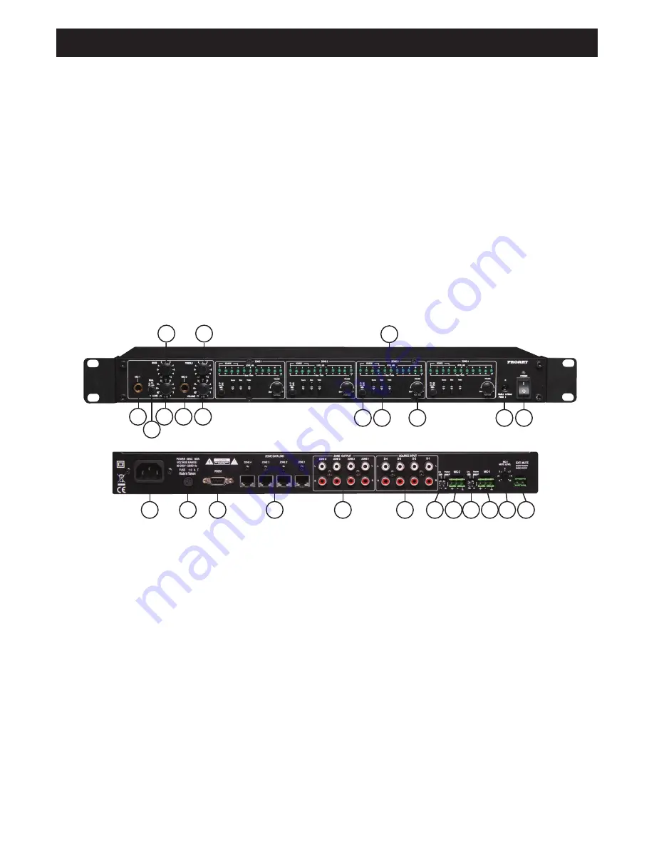
1. Power on / off.
Switch to “ON” position to turn power on and to “OFF” to turn
power off. The indicator will remain illuminated when the unit
is switched off via remote control.
2. IR (infra red) receiver windows.
This is for remote control operation. The remote wall plates
also have IR receivers and remote control operation is
identical for the main unit or wall plates.
3. Volume control for channel left and right output.
This volume knob is used to adjust the system output level.
When the volume control is adjusted, each LED indicator has
10 steps / increments, providing a total of 100 increments (ie
0 - 100%) Note there is no balance control in this unit.
Pushing the volume knob provides a channel mute function.
This switch is a toggle function. Pushing once mutes the
channel and pushing again returns the signal to its
former level.
4A.4B. Tone controls (bass and treble).
The centre LED indicator represents 0dB. Each LED indicator
is either a boost or defeat as follows:
1 LED
=2dbB
2 LED’s =4dB
3 LED’s =6dB
4 LED’s =9dB
5 LED’s =12dB
Pressing either the up or down bass or treble selector button
once displays the current setting. Press either up or down to
adjust to the desired setting.
4C. Source input selector.
This selects the input channel that is to be directed to the
output channel being adjusted. Pressing either the up or
down source input selector button once displays the current
input source. Press either up or down to select the desired
source.
Overview
Congratulations on purchasing a Proart matrix mixer. This unit is designed for use in commercial installations such as pubs, clubs,
schools, function centres and the like. It is also suitable for large domestic installations.
The unit allows any combination of 4 auxiliary and 2 microphone / line inputs to be routed to any of 4 output zones.
• Any combination of 4 auxiliary and 2 microphone / line
inputs can be routed to any of 4 output zones.
• Separate bass and treble controls for all inputs
• Front mounted mic inputs and volume controls. Plus rear
mic / line inputs(switch selectable).
• Phantom power available for rear mic inputs
• Switch selectable on / off microphone muting
• Adjustable mic muting level.
• Separate rear mounted switch contact for mute control
• Separate microphone on / off switches for each zone
• LED level meters for volume setting
• LED level meter indication for bass and treble setting
• LED indication for source selection.
• Complete functionality via RS232 control
• 2 way RS232 communication
• Infra red remote control (supplied with main unit)
• Remote source volume controls (optional A 5432)
• Industry standard Cat 5e wiring for remote source volume
controls.
7
10
8
Installation
See Fig. 4 for typical installation and set up.
7
8
9
Features
Controls & Operation


