background image

1.1 INTRODUCTION


Instruction 

Main features 


Welding positioned is normally used in the rotating and welding of the pipe or round 
work pieces. 


It can be applied on all kinds of welding: SMAW, MIG, TIG, Plasma, etc. 


It can adopt different fixture to get the welding effects you require. 


The table can be tilted for 0~135°, which is convenient for all angles of the pipe welding 
or for adjusting welding angles. (It can adopt either manual or electrical operation.) 


The table has a through hole of

ψ

1”, which is convenient for the long pipe welding or 

the purge shielding gas. 


On the table, there are 4 slots, suitable for all kinds of grippers. 


Farthing current

800Amps 100%.(PT-1000 For 400Amps) 


All units are high frequency protected. 


Содержание PT-1000

Страница 1: ...ODEL PT 1000 PT 2000 WELDING POSITIONER Serial Number 18009001 and later Date Oct 04 2018 UNITED PROARC CORPORATION No 3 Gungye 10th Road Pingjen Industrial Park Tel No 886 3 4696600 Pingjen City Taoyuan 324 Taiwan Fax No 886 3 4694499 http www proarc com tw E Mail customerservice proarc com tw RD 8422BE ...

Страница 2: ......

Страница 3: ...ion 4 3 2 Sequence diagram 5 4 1 Trouble shooting guide 6 5 1 Part List Machine PT 1000 8 5 2 Part List Machine PT 2000 10 5 3 1 Part List Ground kit PT 1000 12 5 3 2 Part List Ground kit PT 2000 13 5 4 Part List Control box 14 6 1 Control system box 16 6 2 Main circuit 17 6 3 Pendant control circuit 18 6 4 Inside input output connect interface 19 6 5 Input output connect interface 22 A Rotation p...

Страница 4: ...e information concerning damage claims or mistakes in shipment to United ProArc Corporation No 3 Gungye 10th Road Pingjen Industrial Park Pingjen City Taoyuan 324 Taiwan Include the quipment identification number along with a description of the parts in question Move the equipment to the installation site before uncrating the unit Use care to avoid damaging the equipment when using bars hammers et...

Страница 5: ...Interventions Before control and repair see the apparatus is switched off and insulated Connection with fixed installation cable is impossible Switch off by fixed connection is multi polar phase and neutral It s on Stop and connection is impossible Some apparatus are provided with starting circuit HT HF with a plate Never enter into the corresponding switch cupboard Only qualified persons are auth...

Страница 6: ... option of the defected part only ProArc s option to repair or replacement of a defected part under this warranty shall be based on FOB Taiwan basis UNITED PROARC CORPORATION shall not be liable for any loss or consequential damage or express accruing directly or indirectly from the use of equipment covered by this warranty This warranty supersedes all previous ProArc warranties and is exclusive w...

Страница 7: ...ing effects you require The table can be tilted for 0 135 which is convenient for all angles of the pipe welding or for adjusting welding angles It can adopt either manual or electrical operation The table has a through hole ofψ1 which is convenient for the long pipe welding or the purge shielding gas On the table there are 4 slots suitable for all kinds of grippers Farthing current 800Amps 100 PT...

Страница 8: ... of gravity mm 400 300 Rated eccentricity mm 200 300 Table diameter D mm ψ600 ψ800 Rotation speed rpm 0 05 1 0 05 1 Spindle thru hole mm 26 35 Ear thing Amp 400 800 Tilt range deg 0 135 Tilt speed 135 deg sec 45 58 Overall length A mm 850 1 190 Overall width B mm 900 1 190 Overall height C mm 700 990 Center to floor AD type mm 600 600 975 855 855 1300 Weight kg 232 750 ...

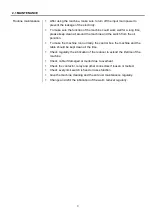
Страница 9: ...tion To make the machine run normally the control box the machine and the table should be kept clean all the time Check regularly the lubrication of the reducer to extend the lifetime of the machine Check cable if damaged or melted due to overheat Check the contactor relay and other connectors if loosen or melted Check every limit switch is fixed or loses function Give the machine cleaning and the...

Страница 10: ...switch Test Weld Weld The welding output of JN1 is activated when pressing Run button of remote control device Test The welding output of JN1 is always off 7 Remote control device A Speed meter Shows the speed data Hz B Speed knob To increase speed turn clockwise To decrease speed turn counter clockwise C Forward Reverse Indicates forward and reverse direction of the table Caution While turning pl...

Страница 11: ...5 3 2 SEQUENCE DIAGRAM ...

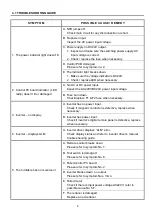
Страница 12: ... power input voltage B Fuse burn down Check replace F1 F2 fuse when necessary 3 Inverter no display A Inverter has no power input Check if magnetic contactor is defective replace when necessary B Inverter has power input Check if inverter s digital remote panel is defective replace when necessary 4 Inverter displays ALM A Inverter driver displays ALM error Check display status and refer to inverte...

Страница 13: ...ower voltage AC220V refer to possible cause No 6 F F The reducer is damaged Replace a new reducer 7 Remote switch has no action or speed control knob disable A Snap switch damaged Check replace the snap switch contactor if necessary B Potentiometer damaged Measure the potentiometer resistance 5KΩ replace a new one if needed C Indicator not working Change the indicator 8 Foot remote speed control d...

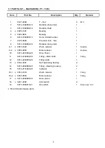
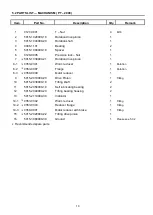
Страница 14: ...ion 1 9 1 0353 0320 Worm reducer 1 Rotation 9 2 0350 0040 Motor reducer 1 Rotation 10 5014 2010000 20 Drive Pinion 1 11 5014 2160000 20 Tilting Main shaft 1 Tilting 12 5014 2030000 20 Tilting shaft 1 13 0332 3501 Self lubricating bearing 2 14 5014 2040000 20 Tilting Bearing housing 2 15 5015 2110000 20 Indicator 1 16 1 0353 0319 Worm reducer 1 Tilting 16 2 0350 0052 Motor reducer 1 Tilting 17 5014...

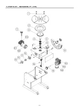
Страница 15: ...9 5 1 PARTS LIST MACHANISM PT 1000 ...

Страница 16: ...reducer 1 Rotation 8 2 0353 0307 Flange 1 Rotation 8 3 0350 0049 Motor reducer 1 9 5015 2010000 20 Drive Pinion 1 Tilting 10 5015 2030000 10 Tilting shaft 2 11 5015 2050000 10 Self lubricating bearing 2 12 5015 2040000 20 Tilting bearing housing 2 13 5015 2110000 30 Indicator 1 14 1 0353 0342 Worm reducer 1 Tilting 14 2 0353 0343 Reducer flange 1 Tilting 14 3 0350 0001 Motor reducer with brake 1 T...

Страница 17: ...11 5 2 PARTS LIST MACHANISM PT 2000 ...

Страница 18: ...y Remark 1 5010 2050102 10 Carbon brush 1 2 0144 0028 Spring 2 3 5010 2040100 20 PE plastic body 1 4 0106 0805 Hex cap screws cupper 1 5 0121 0804 Washer cupper 2 6 4000 274859 Terminal 1 7 0123 0802 Nut cupper 1 8 5015 3080020 21 Ground kit 1 Recommended spare parts ...

Страница 19: ...50102 10 Carbon brush 2 2 5010 2040400 10 PE plastic body 1 3 5010 2040500 10 PE plastic body 1 4 0144 0028 Spring 4 5 4000 274859 Terminal 1 6 0106 0805 Hex cap screws cupper 1 7 0121 0804 Washer cupper 2 8 0123 0802 Nut cupper 1 9 5015 3080000 30 Ground kit 1 Recommended spare parts ...

Страница 20: ...3214 1005 Contact 1 13 3214 4006 Push button 1 PB1 14 3216 1003 Rotaries switch 1 CS1 15 3122 7002 Female socket 17Pin 1 JN4 16 3122 4003 Female socket 7PiN 2 JN2 JN3 3121 4003 Male plug 7Pin 2 JN2 JN3 17 3124 2005 Male socket 4Pin 1 3123 2005 Female plug 4Pin 1 18 3534 3005 Power cable gland 1 P1 19 3122 4004 Female socket 10Pin 1 JN5 3121 6002 Male plug 10PiN 1 JN5 20 3123 3003 Female plug 4Pin ...

Страница 21: ...15 5 4 PARTS LIST CONTROL BOX ...

Страница 22: ...16 6 1 CONTROL SYSTEM BOX ...

Страница 23: ...17 6 2 MAIN CIRCUIT ...

Страница 24: ...18 6 3 PENDANR CONTROL CIRCUIT ...

Страница 25: ... INV2 B2 5 5 FAN1 6 6 FAN2 CN1 Connector CN3 Connector Inverter 2 Description Inverter 1 Description 1 1 RA 1 1 RA 2 2 RB 2 2 RB 3 3 RC 3 3 RC CN2 Connector CN4 Connector Inverter 2 Description Inverter 1 Description 1 1 M0 1 1 M0 2 2 M1 2 2 M1 3 3 M2 3 3 M2 4 4 M3 4 4 M3 5 5 M4 5 5 M4 6 6 M5 6 6 M5 7 7 GND 7 7 GND 8 9 AFM 8 8 AFM 9 9 AVI 9 9 AVI 10 10 10V 10 10 10V 11 11 MCM 11 11 MCM 12 12 M01 1...

Страница 26: ...W1 1 1 1 LS DN1 2 2 R1 2 2 2 LS DN2 3 3 NC 3 3 LS UP1 4 4 NC 4 4 LS UP2 5 5 NC CN7 Connector CN8 Connector Hand Pendant Description Remote Foot Switch Description 1 1 AFM1 1 1 RMV 2 2 GND1 2 2 GND1 3 3 AVI1 HP 3 3 RMI 4 4 10V1 4 4 GND1 5 5 GND1 5 5 M10 RF 6 6 M12 6 6 GND1 7 7 M10 HP 8 9 M11 9 9 M13 10 10 NC 11 11 ES 1 12 12 ES 2 ...

Страница 27: ...CE PCB1 CN10 Connector CN11 Connector Front SW Description MC Description 1 1 PB1 1 1 1 MC A1 2 2 PB1 2 2 2 MC A2 3 3 L1 1 3 3 MC C1 4 4 L1 2 4 4 MC C2 5 5 DN1 CN11 3 6 6 DN2 CN10 1 7 7 UP1 8 9 UP2 9 9 SW1 1 10 10 SW1 2 11 11 SW2 1 12 12 SW2 2 ...

Страница 28: ...on 1 1 SW1 1 1 U1 2 2 R1 2 2 V1 3 3 NC 3 W1 4 G 5 3 INV1 F1 6 4 INF1 F2 7 JN3 Connector JN4 Connector PCB J3 Description PCB CN7 Description 1 U2 1 1 AFM1 2 V2 2 2 GND1 3 W2 3 3 AVI1 HP 4 G 4 4 10V1 5 3 INV2 B1 5 5 GND1 6 4 INF2 B2 6 6 M12 7 7 7 M10 HP 8 8 M11 9 9 M13 10 10 NC 11 11 ES 1 12 12 ES 2 13 14 15 16 17 G ...

Страница 29: ...23 6 5 INPUT OUTPUT CONNECT INTERFACE CONTROL BOX JN5 Connector PCB CN8 Description 1 4 GND1 2 3 RMI 3 1 RMV 4 5 M10 RF 5 2 GND1 6 6 GND1 7 8 9 10 G ...

Страница 30: ... Pr 30 DC Braking during stopping 0 3 18 Pr 32 Momentary power loss operation selection 00 19 Pr 36 Upper Bound of output frequency 120 20 Pr 37 Lower Bound of output frequency 1 5 21 Pr 38 Multi function input terminal M0 M1 01 22 Pr 40 Multi function input terminal M3 09 23 Pr 45 Multi function output terminal 1 00 24 Pr 46 Multi function output terminal 2 07 25 Pr 54 Torque compensation 00 26 P...

Страница 31: ...ration time 2 Taccel 2 1 11 1 12 Deceleration time 2 Tdecel 2 1 12 1 14 Jog Frequency 73 72 13 1 15 Auto Acceleration Deceleration 0 14 1 16 S Curve in Accel 3 15 1 17 S Curve in Decel 3 Item No Group 2 Operation method parameter Setting Value PT 1000 PT 2000 16 2 00 Source of frequency 0 17 2 01 Source of operation command 1 Item No Group 4 Input function parameter Setting Value PT 1000 PT 2000 4...

Страница 32: ...26 CIRCUIT DIAGRAM ...

Отзывы: