


X K 3 1 9 0 - A 9+
6
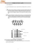
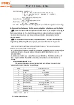
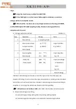
shown in graph 2-3.
2.
If 4-core shielded cable is used, +S must be short connected with +E, so did -S and
-E.
3.
▲
!
Indicator must be reliably connecting to Load cell and shielded-cable of load
cell must be reliably connected to underground. If indicator is powered on,
the user should not plug or unplug in order to protect the indicator and load
cell.
4.
▲
!
Load cell and indicator are static sensitive devices; you must adopt anti-static
measures. In order to protect the operator, indicator, and relevant devices,
you should install lightning rod in the thunderstorm frequently happening
area
Graph 2-3: Connection of the load cell
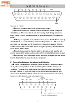
III. Connection between Printer and Indicator
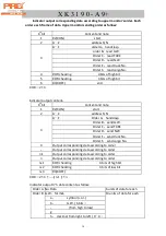
1. The printing interface adopts the standard parallel interface. The 25-pin RS232
socket is illustrated below:
5 Shield
8 -IN
9 +IN
1 -E
2 -S
7 +S
6 +E
+
_
Terminal of Indicator
Terminal of Sensor
Bridge of Power Supply
Signal Output
1
2
3
4
5
6
7
8
9
-E
-S
Shield
+E
+S
-IN
+IN
Содержание XK3190-A9+
Страница 1: ...XK3190 A9 Weighing Indicator USER S MANUAL...


