Pro-tec 193762 Скачать руководство пользователя страница 1

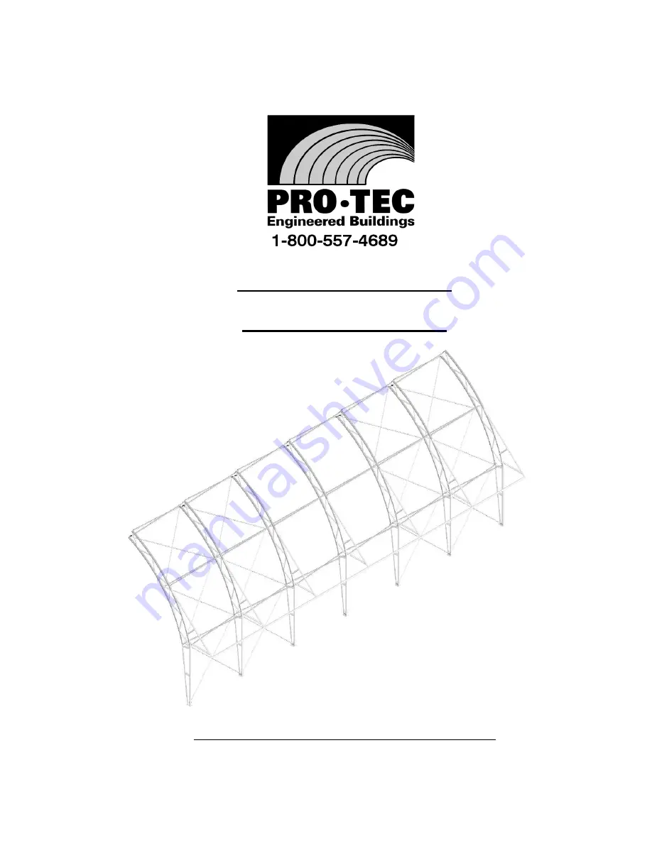
PRO-TEC SENTRY BUILDING

AWNING MANUAL

IMPORTANT - TO THE DEALER OR ERECTOR:

RETURN THIS MANUAL TO THE OWNER FOR THEIR FUTURE REFERENCE

SIOUX STEEL COMPANY, P.O. BOX 1265, SIOUX FALLS, SOUTH DAKOTA 57101

1-800-557-4689

MANUAL NO. 193762

REV D/MRS 8/1/17 ECN 17-141

Содержание 193762

Страница 1: ...ING MANUAL IMPORTANT TO THE DEALER OR ERECTOR RETURN THIS MANUAL TO THE OWNER FOR THEIR FUTURE REFERENCE SIOUX STEEL COMPANY P O BOX 1265 SIOUX FALLS SOUTH DAKOTA 57101 1 800 557 4689 MANUAL NO 193762 REV D MRS 8 1 17 ECN 17 141 ...

Страница 2: ...NG FRAME PAGE 7 70 AWNING FRAME PAGE 8 80 AWNING FRAME PAGE 9 90 AWNING FRAME PAGE 10 EAVE INSTALLATION PAGE 11 40 TO 50 RATCHET MOUNT INSTALLATION PAGE 12 60 TO 80 RATCHET MOUNT INSTALLATION PAGE 13 90 RATCHET MOUNT INSTALLATION PAGE 14 COVER SPLICE BRACKET PAGE 15 MAINTENANCE SCHEDULE PAGE 16 17 WARRANTY STATEMENTS PAGE 18 1 ...

Страница 3: ...e erection equipment and proper training in the operation of this equipment are important factors for the safe erection of building Reading understanding and following the instructions in this book are also very important for the safe assembly of this building Sioux Steel Company includes all reasonable means for accident prevention except a safe and careful operator If any decals become damaged d...

Страница 4: ...ocket wrench size 3 8 3 4 Impact Wrench pneumatic or electric Special Tools Movable scaffolding or man lift Material Customer Supplied Duct Tape BOLT INSTALLATION Bolts should be installed to a snug tight condition which is defined as the tightness attained by either a few impacts of an impact wrench or the full effort of a worker with a wrench that brings the connected plates in to a firm contact...

Страница 5: ...GED EAVE 3 193389GRY 10FT 194100GRY 12FT 189988GRY 16FT 2 MOUNT 40 TO 80 189992GRY 90 194105GRY UPPER TUBE 157630 DRILL SCREW 1 4 x 1 1 4 COMPONENTS 189515 1 2 NYLOCK NUT SCALE 1 2 2 MOUNT PLATE USED ON END RAFTERS 90 194104GRY 40 TO 80 189993GRY BRACE ARM 163753 1 2 x 4 BOLT SCALE 1 2 191750 1 2 x 4 1 2 BOLT SCALE 1 2 HORIZONTAL ARM 4 ...

Страница 6: ...ube as shown in drawing by drilling 17 32 clearance hole into rafter and then securing with 1 2 bolt and nut Step 1 2 Assemble Horizontal Arm and Brace Arm to Upper Tube utilizing existing pre drilled holes and 1 2 bolts and nuts as shown in drawing Step 1 3 Utilizing 1 4 drill screws attach Horizontal Arm and Brace Arm to rafter as shown in drawing Step 1 4 Proceed to step 2 STEP 1 40 AWNING FRAM...

Страница 7: ... ARM Step 1 4 Proceed to step 2 in drawing HOLES PRE DRILLED BOLT 1 2 X 3 1 2 DRILL SCREWS 8 1 4 X 1 1 4 Step 1 1 Install Upper Tube as shown in drawing by drilling 17 32 clearance hole into rafter and then securing with 1 2 bolt and nut Step 1 2 Assemble Horizontal Arm and Brace Arm to Upper Tube utilizing existing pre drilled holes and 1 2 bolts and nuts as shown in drawing Step 1 3 Utilizing 1 ...

Страница 8: ...OLT 1 2 X 4 Step 1 1 Install Upper Tube as shown in drawing by drilling 17 32 clearance hole into rafter and then securing with 1 2 bolt and nut Step 1 2 Assemble Horizontal Arm and Brace Arm to Upper Tube utilizing existing pre drilled holes and 1 2 bolts and nuts as shown in drawing Step 1 3 Utilizing 1 4 drill screws attach Horizontal Arm and Brace Arm to rafter as shown 1 2 NUT 1 2 X 3 1 2 BOL...

Страница 9: ...tep 1 1 Install Upper Tube as shown in drawing by drilling 17 32 clearance hole into rafter and then securing with 1 2 bolt and nut Step 1 2 Assemble Horizontal Arm and Brace Arm to Upper Tube utilizing existing pre drilled holes and 1 2 bolts and nuts as shown in drawing Step 1 3 Utilizing 1 4 drill screws attach Horizontal Arm and Brace Arm to rafter as shown DRILL 17 32 1 2 NUT HOLE 1 2 X 4 BOL...

Страница 10: ...tep 1 1 Install Upper Tube as shown in drawing by drilling 17 32 clearance hole into rafter and then securing with 1 2 bolt and nut Step 1 2 Assemble Horizontal Arm and Brace Arm to Upper Tube utilizing existing pre drilled holes and 1 2 bolts and nuts as shown in drawing Step 1 3 Utilizing 1 4 drill screws attach Horizontal Arm and Brace Arm to rafter as shown UPPER TUBE ARM HORIZONTAL BRACE ARM ...

Страница 11: ...ep 1 1 Install Upper Tube as shown in drawing by drilling 17 32 clearance hole into rafter and then securing with 1 2 bolt and nut Step 1 2 Assemble Horizontal Arm and Brace Arm to Upper Tube utilizing existing pre drilled holes and 1 2 bolts and nuts as shown in drawing Step 1 3 Utilizing 1 4 drill screws attach Horizontal Arm and Brace Arm to rafter as shown UPPER TUBE ARM HORIZONTAL BRACE ARM 1...

Страница 12: ...d install Eave 3 as shown in drawing Secure with 1 4 drill screws from underneath at insert connections Step 2 2 Next install Swaged Eave 3 as shown in drawing Secure with 2 1 4 drill screws from underneath at swage and insert connections Step 2 3 Install 3 Tube Caps into end of Eave Tubes as shown in drawing Step 2 4 Duct tape all drill screws and swage connections to prevent abrasion to cover 3 ...

Страница 13: ...ter Rafter detail below Step 3 3 Next secure 2 Mount Plates and 2 Mounts to rafter utilizing 4 1 4 drill screws as shown on drawing Step 3 1 Install 1 2 Mount Plate and 1 2 Mount to each End Rafter by utilizing 189993GRY 2 MOUNT PLATE 189992GRY 2 MOUNT 1 2 x 3 1 2 BOLT 190006 1 2 NYLOCK NUT 189515 1 4 x 1 1 4 DRILL SCREW 157630 4 1 2 NYLOCK CENTER RAFTER BOLT 4 1 2 x 3 1 2 NUT 2 1 4 X 1 1 4 DRILL ...

Страница 14: ...e 2 Mount Plates and 2 Mounts to rafter utilizing 4 1 4 drill screws as shown on drawing 189993GRY 2 MOUNT PLATE 189992GRY 2 MOUNT 1 2 x 4 BOLT 163753 1 2 NYLOCK NUT 189515 1 4 x 1 1 4 DRILL SCREW 157630 STEP 3 60 TO 80 RATCHET MOUNT INSTALLATION 4 1 2 NYLOCK NUT RH END RAFTER 2 1 4 X 1 1 4 DRILL SCREW BOTH SIDES 4 1 2 x 4 BOLT LH END RAFTER NYLOCK NUT 4 1 2 2 1 4 X 1 1 4 DRILL SCREW BOTH SIDES 4 ...

Страница 15: ...ts to rafter utilizing 4 1 4 drill screws Step 3 1 Install 1 2 Mount Plate and 1 2 Mount to each End Rafter by utilizing 194104GRY 2 MOUNT PLATE 194105GRY 2 MOUNT 1 2 x 4 1 2 BOLT 191750 1 2 NYLOCK NUT 189515 1 4 x 1 1 4 DRILL SCREW 157630 DRILL SCREW BOTH SIDES RH END RAFTER NUT NYLOCK 4 1 2 2 1 4 X 1 1 4 4 1 2 x 4 1 2 BOLT 4 1 2 NYLOCK LH END RAFTER BOLT 4 1 2 x 4 1 2 NUT 2 1 4 X 1 1 4 DRILL SCR...

Страница 16: ...gle 193651GRY on upper chord of rafter at splice location as shown below utilizing 4 1 4 x 1 1 4 Drill Screws 157630 Note Mount angle is used for 2 Conestoga ratchets at splice location See Cover manual for additional details DETAIL A SCALE 1 16 193651GRY MOUNT ANGLE 1 3 1 4 APPROX RAFTER AT SPLICE LOCATION 15 ...

Страница 17: ... c Check all base plate anchor studs and nuts to assure they are tight d Check all ratchet mount and winch bolts and nuts to assure they are tight e Check for premature wear of fabric cover especially where tension is applied and where there is direct contact with the buildings steel frame f Check for premature deterioration of the corrosion protection on the building components NOTE Building cove...

Страница 18: ...HAT IS NOT WARRANTED Sioux Steel does not warrant and is not responsible for the following 1 used products 2 modification or alteration of the Products 3 Products that have not been properly installed or not installed in accordance with the instruction manual improper assembly or improper construction by any persons other than Sioux Steel employees 4 depreciation damage or loss caused by the use o...

Отзывы: