background image

18

HOW TO USE A HEART RATE WORKOUT

1. Press any button on the console or begin ped-

aling to turn on the console.

See step 1 on page 15.

2. Select a heart rate workout.

To select one of the heart rate workouts, press the

Heart Rate 1 or the Heart Rate 2 button on the left

side of the console.

3. Enter a target heart rate setting.

A few seconds after

you select a heart rate

workout, the target

heart rate setting for the

workout will flash in the

lower right display.

During heart rate workout 1,

the same target

heart rate setting will be programmed for all seg-

ments of the workout. If you have selected heart

rate workout 1, press the increase and decrease

buttons above the Heart Rate buttons to enter the

desired target heart rate setting (see EXERCISE

INTENSITY on page 22).

During heart rate workout 2,

different target

heart rate settings will be programmed for different

segments of the workout. If you have selected

heart rate workout 2, press the increase and

decrease buttons above the Heart Rate buttons to

enter the desired maximum target heart rate set-

ting for the workout (see EXERCISE INTENSITY

on page 22).

4. Hold the handgrip pulse sensor.

It is not necessary to hold the handgrip pulse sen-

sor continuously during heart rate workouts; how-

ever, you should hold the handgrip pulse sensor

frequently for the workouts to operate properly.

Each time you hold the handgrip pulse sensor,

keep your hands on the metal contacts for at

least 30 seconds.

5. Begin pedaling to start the workout.

Heart rate workout 1

is divided into 40 one-

minute segments. Note: For a shorter workout,

stop exercising or select a different workout before

the workout ends.

Heart rate workout 2

is divided into 30 one-

minute segments. One target heart rate setting is

programmed for each segment. Note: The same

target heart rate setting may be programmed for

consecutive segments.

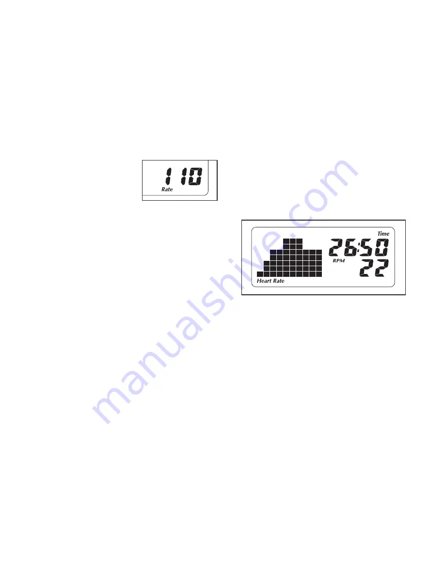
During the workout, the workout profile in the dis-

play will show your progress. The flashing seg-

ment of the profile represents the current segment

of the workout. The height of the flashing segment

indicates the target heart rate setting for the cur-

rent segment. At the end of each segment of the

workout, a series of tones will sound and the next

segment of the profile will begin to flash.

During both workouts,

the console will regularly

compare your heart rate to the target heart rate

setting for the current segment of the workout. If

your heart rate is too far below or above the target

heart rate setting, the resistance of the pedals will

automatically increase or decrease to bring your

heart rate closer to the target heart rate setting.

Each time the resistance changes, the resistance

level will appear in the display for a few seconds

to alert you.

Содержание StrideClimber 490

Страница 1: ...er in the space above for reference USER S MANUAL www proform com QUESTIONS If you have questions or if parts are damaged or missing DO NOT CONTACT THE STORE please contact Customer Care IMPORTANT Ple...

Страница 2: ...PLODED DRAWING 25 ORDERING REPLACEMENT PARTS Back Cover LIMITED WARRANTY Back Cover 2 WARNING DECAL PLACEMENT This drawing shows the location s of the warning decal s If a decal is missing or illegibl...

Страница 3: ...5 kg 8 Wear appropriate exercise clothes while exercising do not wear loose clothes that could become caught on the elliptical exer ciser Always wear athletic shoes for foot protection 9 Hold the uppe...

Страница 4: ...e your workouts at home more effective and enjoyable For your benefit read this manual carefully before you use the elliptical exerciser If you have ques tions after reading this manual please see the...

Страница 5: ...le the elliptical exerciser use the drawings below to identify small parts The number in parenthe ses below each drawing is the key number of the part from the PART LIST near the end of this manual Th...

Страница 6: ...two M8 x 25mm Washers 54 Do not tighten the Button Screws yet 1 Tip It may be easier to do this step if you loosen the two Leveling Feet 9 at the rear of the Track 2 Orient the Track Cover 7 and the...

Страница 7: ...nto the Frame 1 Attach the Upright with two M8 x 16mm Button Screws 53 and two M8 x 35mm Button Screws 80 Do not tighten the Button Screws yet 3 3 1 73 53 80 53 80 Avoid pinching the Wire Harness 73 d...

Страница 8: ...it to warm to room temperature before inserting batteries If you do not do this you may damage the console displays or other elec tronic components Press the two tabs on the battery cover and remove i...

Страница 9: ...not shown and the Left Pedal Leg not shown 7 37 Grease 38 39 71 8 Apply a generous amount of grease to the axle on the Right Upper Body Leg 37 and to the right Crank Arm 31 Next apply a small amount o...

Страница 10: ...x 20mm Button Screw 58 a Small Axle Cover 46 and an M10 x 25mm Washer 52 Repeat this step for the other side of the elliptical exerciser 9 31 10 Tighten the two M8 x 16mm Button Screws 53 and the two...

Страница 11: ...e left until the Rollers are centered on the Track See step 2 With the help of another person tighten the M8 x 50mm Button Screws 65 and the M8 x 16mm Button Screws 53 12 Make sure that all parts of t...

Страница 12: ...s eliminated HOW TO EXERCISE ON THE ELLIPTICAL EXERCISER To mount the elliptical exerciser hold the upper body arms and step onto the pedal that is in the lower posi tion Then step onto the other peda...

Страница 13: ...l path or a more horizontal path To adjust the elliptical exerciser so that the pedals move in a more vertical path pivot the two selectors to the high position to adjust the elliptical exerciser so t...

Страница 14: ...near target heart rate settings while you exercise The console features the iFit Interactive Workout System which enables the console to accept iFit cards containing workouts designed to help you ach...

Страница 15: ...tance level of the ped als The display will change modes every few sec onds The display will also show your heart rate when you use the handgrip pulse sensor see step 5 on page 16 The left display wil...

Страница 16: ...squeeze the metal contacts tightly For optimal performance clean the metal contacts using a soft cloth never use alcohol abrasives or chemi cals to clean the contacts 6 Turn on the fan if desired The...

Страница 17: ...flash If a differ ent resistance level is programmed for the next segment the resistance level will appear in the display for a few seconds to alert you The resis tance of the pedals will then change...

Страница 18: ...should hold the handgrip pulse sensor frequently for the workouts to operate properly Each time you hold the handgrip pulse sensor keep your hands on the metal contacts for at least 30 seconds 5 Begin...

Страница 19: ...ont cover of this manual iFit cards are also available at select stores 1 Press any button on the console or begin ped aling to turn on the console See step 1 on page 15 2 Insert an iFit card and sele...

Страница 20: ...ld Loosen but do not remove the three M6 x 25mm Button Screws 61 Insert the shaft of a screw driver downward between the Idler 12 and the pul ley located on the Eddy Mechanism 10 Pull the top of the s...

Страница 21: ...on page 16 HOW TO LEVEL THE ELLIPTICAL EXERCISER If the elliptical exerciser rocks slightly on your floor during use turn one or all of the leveling feet beneath the track until the rocking motion is...

Страница 22: ...your goal is to strengthen your cardiovascular system you must perform aerobic exercise which is activity that requires large amounts of oxygen for prolonged periods of time For aerobic exercise adju...

Страница 23: ...lles Stretch With one leg in front of the other reach forward and place your hands against a wall Keep your back leg straight and your back foot flat on the floor Bend your front leg lean forward and...

Страница 24: ...ctor Bushing 48 2 Selector Axle 49 4 M10 x 16mm Button Screw 50 2 Key 51 14 M6 x 12mm Button Screw 52 8 M10 x 25mm Washer 53 12 M8 x 16mm Button Screw 54 10 M8 x 25mm Washer 55 4 M8 Split Washer 56 2...

Страница 25: ...Model No PFEL04909 0 R1109A 22 23 24 25 26 27 28 28 29 30 31 32 33 34 35 42 43 44 45 45 45 45 46 46 44 50 51 54 52 52 77 58 58 61 77 53 53 67 69 70 71 72 72 72 72 72 66 71 54 54 60 78 74 54 47 47 5 49...

Страница 26: ...1 2 3 4 6 7 8 8 9 9 9 10 11 12 13 14 15 15 16 17 18 18 19 19 20 21 53 53 55 55 56 56 57 57 53 53 59 61 62 63 64 64 53 75 75 72 76 73 65 54 68 75 79 80 80 EXPLODED DRAWING B Model No PFEL04909 0 R1109...

Страница 27: ...1 32 34 36 37 39 40 41 42 43 44 45 45 46 44 50 51 54 52 77 58 61 77 53 53 69 70 71 72 72 66 78 54 54 74 26 35 38 45 45 46 52 58 51 60 71 54 47 47 5 49 52 49 52 48 51 51 67 EXPLODED DRAWING C Model No...

Страница 28: ...warranty does not extend to any damage to a product caused by or attributable to freight damage abuse misuse improper or abnormal usage or repairs not provided by an ICON authorized service center to...

Отзывы: