background image

4

ASSEMBLY 

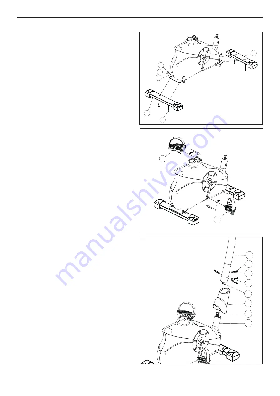
STEP 1

Lift  the  front  of  the  main  frame  and  fit  the  Front 

Stabilizer (65) with 2 x Carriage Bolts (41), 2 x 

Curved Washers (36), 2 x Spring Washers (71) and 

2 x Cap Nuts (35). Now repeat this process for the 

Rear Stabilizer (40).

STEP 2 

Attach right pedal (26R) on the right pedal crank. 

(NOTE: The screw direction is clockwise). 

Now repeat this process for the left pedal (26L).

(NOTE: The screw direction is anti-clockwise).

Then mount the pedal straps left and right on the 

associated pedals. 

Note : The pedals are signed with “L” for left 

and “R’ for Right.

STEP 3

Carefully lift the Handlebar Post (72) until it is verti-

cal. Slide the front plastic cover (68) onto handle-

bar post (72). Join the upper Computer Cable (69) 

to the lower Computer Cable (67). Then put the 

Handlebar Post into Main Frame, and secure them 

with 4 Curved Washers (36), 4 Spring Washers 

(71) and 4 Allen Bolts (70).

35

71

40

41

65

36

26L

26R

35

71

40

41

65

36

26L

26R

68

69

71

36

70

67

66

72

Содержание PFIVEX5703.0

Страница 1: ...MANUAL Visit our website www iconsupport eu QUESTIONS If you have questions or if there are missing parts please contact us UK Call 08457 089 009 From Ireland 053 92 36102 Website www iconsupport eu...

Страница 2: ...ING DECAL PLACEMENT 1 IMPORTANT PRECAUTIONS 2 BEFORE YOU BEGIN 3 ASSEMBLY 4 CONSOLE FEATURES 6 HOW TO OPERATE THE BIKE 10 HOW TO MEASURE YOUR PULSE 11 MAINTENANCEANDTROUBLESHOOTING 11 EXERCISE GUIDELI...

Страница 3: ...ighing more than 250 lbs 115 kg 9 Wear appropriate clothes while exercising do not wear loose clothes that could become caught on the elliptical Always wear athletic shoes for foot protection while ex...

Страница 4: ...you use the elliptical If you have questions after reading this manual please see the front cover of this manual To help us assist you note the product model number and serial number before contacting...

Страница 5: ...6L NOTE The screw direction is anti clockwise Then mount the pedal straps left and right on the associated pedals Note The pedals are signed with L for left and R for Right STEP 3 Carefully lift the H...

Страница 6: ...1 into Main Frame Select a suitable height setting and secure in place with the Seat Support Adjuster Knob Note Further more you must ensure when setting this desired position that the seat pillar is...

Страница 7: ...hours and minutes During the setting mode press this button to validate the adjusted values During the STOP mode press this button to reset the values START STOP For a quick start press this button t...

Страница 8: ...rate reading continue to hold the handgrips for about 15 seconds Note If you continue to hold the handgrip pulse sensor the display will show your heart rate for up to 30 seconds The display will then...

Страница 9: ...1 Turn on the console To turn on the console press any button on the console or simply begin pedaling 2 Select your preset program Press the UP and DOWN button to select program 12 to 15 Wait until t...

Страница 10: ...le To turn on the console press any button on the console or simply begin pedaling 2 Select your preset program Press the UP and DOWN button to select program 20 written FAT Wait until the word PROGRA...

Страница 11: ...he seat post upward or downward slightly to make sure that the knob is engaged in one of the adjustment holes in the seat post Then tighten the knob HOW TO ADJUST THE HANDLEBAR To adjust the handlebar...

Страница 12: ...acts Avoid moving your hands or gripping the contacts tightly When you are finished exercising the console will turn off automatically If the pedals do not move for several seconds a tone will sound a...

Страница 13: ...body uses carbohydrate calories for energy Only af ter the first few minutes of exercise does your body begin to use stored fat calories for energy If your goal is to burn fat adjust the intensity of...

Страница 14: ...3 0 1 15 16 17 14 18 23 24 26L 28 29L 30 31L 32 33 34 35 56 55 54 31R 29R 60 61 66 67 68 69 70 22 25 59 58 73 74 36 42 43 44 45 47 48 49 50 37 51 62 53 52 63 72 3R 4 5 6 10 11 12 3L 7 8 2 27 39 40 41...

Страница 15: ...Allen bolt 8 Spring washer Handlebar post Combination wrench Allen key wrench Adaptor Qty 1 2 1 4 1 1 1 1 4 1 1 1 1 2 8 5 2 1 2 1 1 1 1 3 1 2 1 1 1 1 1 1 4 8 1 1 1 1 Item 1 2 3 4 5 6 7 8 9 10 11 12 1...

Страница 16: ...RMATION FOR E U CUSTOMERS This electronic product must not be disposed of in municipal waste To preserve the environment this product must be recycled after its useful life as required by law Please u...

Отзывы: