background image

12

and 1/3 of the “Non-chlorine Shox” bottle to the water
in the spa. Allow the water to circulate for five min-
utes. You should now test the pH level of the water.
Use the included test strips to check the pH of the
water. Refer to the instructions on the test strip pack-
aging to see how to use the test strips.  

If the level is too low, add half of one of the “QUICK
pHix It UP” packets to the water. Let the water circu-
late through the spa jet unit for five minutes. Test the
pH level again. Repeat until the pH level is correct.

If the level is too high, add half of one of the “QUICK
pHix It DOWN” packets to the water. Let the water cir-
culate through the spa jet unit for five minutes. Test
the pH level again. Repeat until the pH level is cor-
rect.

Replace the spa cover and allow the water to contin-
ue to heat.

See WATER CHEMISTRY on page 14 for information
concerning proper water maintenance.

SECURING THE SPA COVER

The spa cover can be secured by snapping the latch-
es on the spa cover into the buckles on the side pan-
els. 

The buckles can be
locked by inserting the
key and turning it
clockwise a quarter
turn. To unlock the
buckles, insert the key
and turn it counter-
clockwise a quarter
turn. 

Always keep the buckles locked when the spa is
not in use. Keep the keys in a safe place, out of
the reach of children.

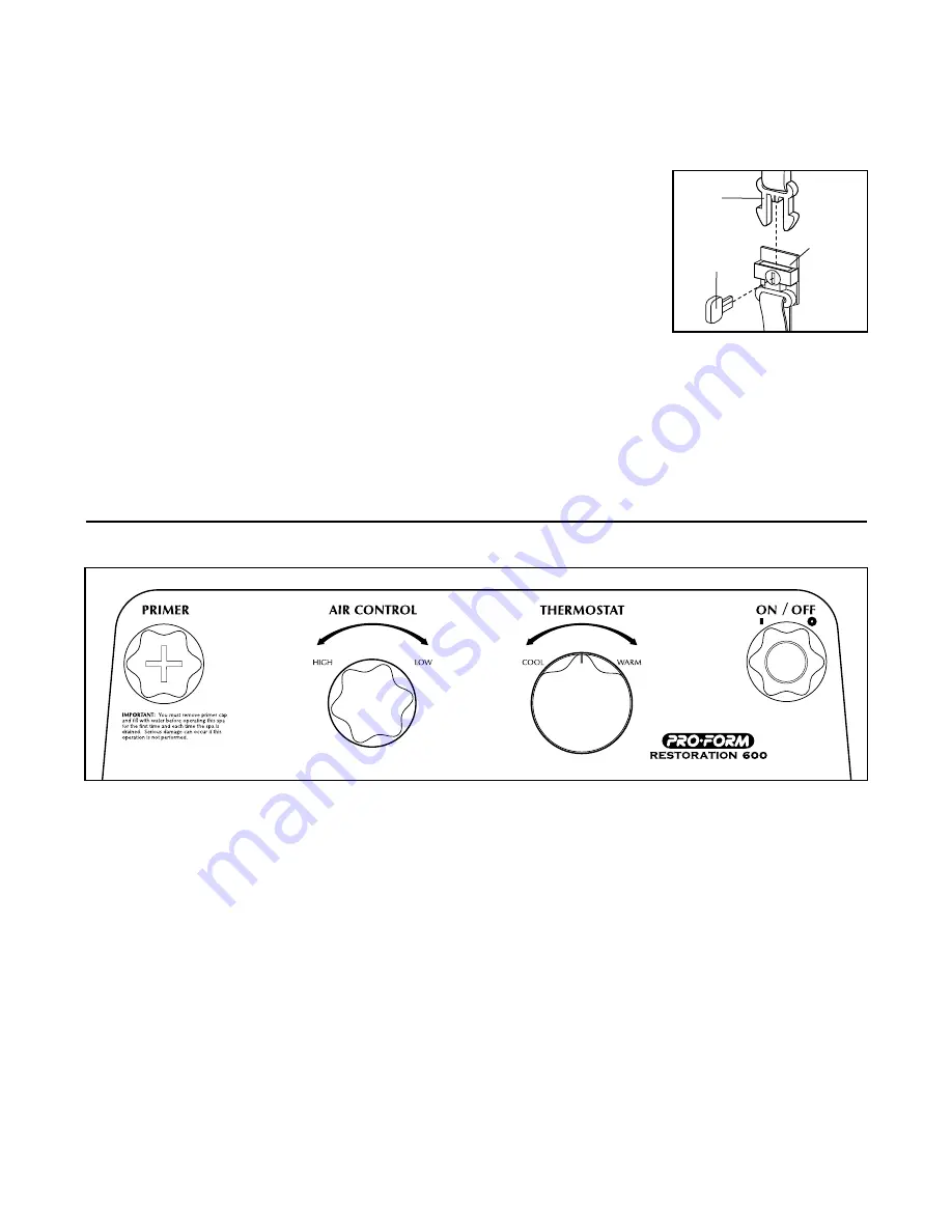
USING THE CONSOLE

Refer to the console diagram above. The function of
each console control is explained below:

Primer: This opening allows you to prime the spa jet
unit before operation (see PRIMING THE SPA JET
UNIT on page 10).

Thermostat: Controls the temperature of the water.
The water heats at about 1.7°F an hour with the cover
on. The thermostat can be set to heat the water from
70°F to 104°F. Use a medical or other accurate ther-
mometer to check the temperature of the water.

On/Off: Turns the spa jet unit on and off. When you
first press the on/off button, the spa jet unit will run at
low speed, providing gentle hydrotherapy. Press the
button again and the spa jet unit will run at high

speed, providing more intense hydrotherapy. Press
the button a third time and the spa jet unit will shut
off. 

The spa jet unit also features an automatic mode,
which heats and filters the water when the spa is left
unattended. When the spa jet unit is first plugged in,
or if the buttons on the console have not been used
for longer than twenty minutes, the automatic mode
will begin filtering or heating the water, as needed.
Note: to keep the filter and heat cycles from run-
ning, the power cord must be unplugged.

Air Control: Determines the amount of air that is in
the spa jet system during operation. If the control is
turned to the left, the amount of air flowing through
the jets will increase. If the control is turned to the
right, the amount will decrease.

DIAGRAM OF THE CONSOLE

Key

Latch

Buckle

Содержание 831.100400

Страница 1: ...OUR TOLL FREE CUSTOMER HOT LINE The trained techni cians on our customer hot line will provide immediate assis tance free of charge to you CUSTOMER HOT LINE 1 888 936 4266 Mon Thu 8 00 am 6 30 pm Fri 8 00 am 6 00 pm EST Model No 831 100400 Serial No Write the serial number in the space above for reference Patent Pending CAUTION Read all precautions and instruc tions in this manual before using thi...

Страница 2: ...the spa shell resulting from exposure to extreme temperatures or damage to the spa shell resulting from exposure to direct sun light and ultraviolet rays while the spa is empty damage to the pump motor plumbing and components due to improper maintenance chemical treatment or exposure damage resulting from failure to proper ly follow user s manual installation operating or maintenance instructions ...

Страница 3: ...ING A LOCATION FOR THE RESTORATION 600 8 ASSEMBLY 9 USING THE RESTORATION 600 11 MAINTENANCE 14 TROUBLE SHOOTING 15 CUSTOMER RECORD 19 ORDERING REPLACEMENT PARTS Back Cover Note A PART LIST and an EXPLODED DRAWING are attached to the center of this manual Remove the PART LIST and EXPLODED DRAWING before beginning assembly 3 ...

Страница 4: ...e any water which may collect on the spa cover 12 Keep children and pets away from the RESTORATION 600 when it is not in use 13 Keep all chemicals away from children and pets 14 The pH and chemical balance of the water must be maintained as explained in this man ual see page 11 Failure to do so may cause injury to users or damage to the spa jet unit and will void the warranty 15 The water pump in ...

Страница 5: ...h their physician before using the RESTORATION 600 Pregnant women should not use the spa if the water temperature is above 100 F 38 C the unborn child could be seriously harmed 28 DANGER To reduce the risk of drowning Prolonged immersion in the RESTORATION 600 may cause hyperthermia a dangerous condition which occurs when the internal body temperature rises several degrees above the normal body te...

Страница 6: ... 600 Locate the labels and familiar ize yourself with this information The label on the side of the spa jet unit is an adhesive decal If this decal is missing or if it is not legible please call our Customer Service Department toll free at 1 888 936 4266 Monday Thursday 8 00 am 6 30 pm Friday 8 00 am 6 00 pm EST excluding holidays to order a replacement decal Apply the decal in the location shown ...

Страница 7: ...RATION 600 If you have additional questions please call our Customer Service Department toll free at 1 888 936 4266 Monday Thursday 8 00 am 6 30 pm Friday 8 00 am 6 00 pm EST excluding holidays To help us assist you please note the product model number and serial number before calling The model number is 830 100400 The serial number can be found on a decal attached to spa jet unit see the front co...

Страница 8: ...t there is room around the RESTORA TION 600 to permit servicing of the unit The diameter of the tub is 69 You should allow for this size plus the size of the spa jet unit when choosing the location 8 Be sure to note any other considerations such as aesthetics or privacy concerns that may affect the safety or enjoyment of using the RESTORATION 600 If you set up the RESTORATION 600 outside 1 You sho...

Страница 9: ...ith the hole in the Fabric Spa Surround Flip the flap on the Fabric Spa Surround 8 over the low section of the Inflatable Spa Liner 9 Be sure that all six cover buckles are fully inserted through the loops in the Fabric Spa Surround 8 3 Remove the power cord from the Spa Jet Unit 13 With the help of a second person place the Spa Jet Unit 13 over the Fabric Spa Surround 8 and the section of the Inf...

Страница 10: ...derside of the Spa Cover 11 See inset drawing A Insert the inflation tube into the hole in the Support Ball 4 Inflate the Support Ball See inset drawing B When the Support Ball 4 is inflated remove the inflation tube from the Support Ball and insert the ball plug through the mesh into the Support Ball The head of the ball plug will hold the Support Ball in place Note The Support Ball 4 is not a to...

Страница 11: ...he GFCI before using the RESTORATION 600 First turn on the RESTORATION 600 by pressing the power button on the console Once the unit is run ning press the GFCI test button The RESTORA TION 600 should shut off Press the reset button The RESTORATION 600 should resume normal oper ation If the RESTORATION 600 continues to run after the test button is pressed then the GFCI is dam aged Do not use the RE...

Страница 12: ...h of children USING THE CONSOLE Refer to the console diagram above The function of each console control is explained below Primer This opening allows you to prime the spa jet unit before operation see PRIMING THE SPA JET UNIT on page 10 Thermostat Controls the temperature of the water The water heats at about 1 7 F an hour with the cover on The thermostat can be set to heat the water from 70 F to ...

Страница 13: ...e pump will begin circulat ing the water for twenty minutes to filter any impuri ties Also if the water temperature falls below 40 F the pump will begin circulating and heating the water to prevent the water from freezing DRAINING THE RESTORATION 600 To drain the RESTORATION 600 you must use a garden hose to siphon the water Place one end of the hose in the spa and hold it in front of a hydro ther...

Страница 14: ...mounts follow the directions on the label closely 5 Keep all containers closed tightly when not in use 6 Never add water to the chemicals always add the chemicals to the water as directed 7 Always store chemicals in a cool dry place MAINTAINING THE PROPER PH BALANCE The pH factor is a measure of relative acidity or alka linity in the water It is measured on a scale of 1 to 14 Pure water has a valu...

Страница 15: ... the room temperature is maintained at 70 F it will take approximately 20 to 28 hours for the water to reach the set temperature b If you are using the RESTORATION 600 out doors it may take longer for the water to heat See the chart below for the approximate heat ing time Air Temperature Heating Time 70 F 20 to 28 hours 50 F 70 F 1 to 2 days 30 F 50 F 2 to 3 days b If the water still has not heate...

Страница 16: ... outdoors in cold weather you must allow the spa to maintain a safe temperature by running in automatic mode Allowing the spa jet unit to freeze will damage the unit If you do not want to use the spa during the winter store it in a warm dry location see WINTER USE AND CARE on page 13 11 SYMPTOM THE WATER LEVEL DROPS a Some water loss due to evaporation is normal If rapid water loss occurs or if yo...

Страница 17: ...17 NOTES ...

Страница 18: ...NOTES 18 ...

Страница 19: ...19 CUSTOMER RECORD Model No Serial No Retailer Name Purchase Date Retailer Address ICON of Canada Inc 900 de l Industrie St Jérôme Québec Canada J7Y 4B8 PLACE STAMP HERE ...

Страница 20: ...many times a week do you exercise Less than 3 times 3 times or more 5 Have you ever purchased an ICON product before Yes No 6 Where did you first see or hear about ICON products Magazine Friend relative Newspaper Ad Store Other 7 What was the primary reason for purchasing this ICON product Store Employee Television Ads Colour Electronic Features Magazine Ads Price Product Design Product Innovation...

Страница 21: ...81 REMOVE THIS EXPLODED DRAWING FROM THE MANUAL ...

Страница 22: ... Electronic Control 26 1 Motor Endcap 27 1 Headrest w Fasteners 28 4 Nut 29 1 Heat Control Nut 30 4 Rubber Insulator Key No Qty Description 31 4 Washer 32 1 Primer O ring 33 1 Rubber Damper 34 1 Wire Harness 35 1 Air Control Knob 36 1 On Off Switch Assembly 37 1 Thermostat Knob 38 1 Primer Cap 39 16 Housing Screw 40 1 Console Overlay 41 1 Micro Switch Wire 42 2 Control Mounting Screw 43 2 Control ...

Страница 23: ... 27 26 33 28 30 31 7 10 1 49 48 38 32 36 35 37 29 17 18 19 42 43 41 44 45 46 50 40 47 15 39 39 12 5 5 6 6 14 21 8 23 24 3 34 48 2 4 51 11 EXPLODED DRAWING Model No 831 100400 R0398A SCHÉMA DÉTAILLÉ No du Modéle 831 100400 ...

Отзывы: