Pro-Form 525 ZLT Скачать руководство пользователя страница 12

12

11

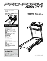
11. Attach the Left and Right Tray Brackets (83, 

84) to the Uprights (66, 76) with four #8 x 3/4" 

Screws (4).

84

4

4

66

83

76

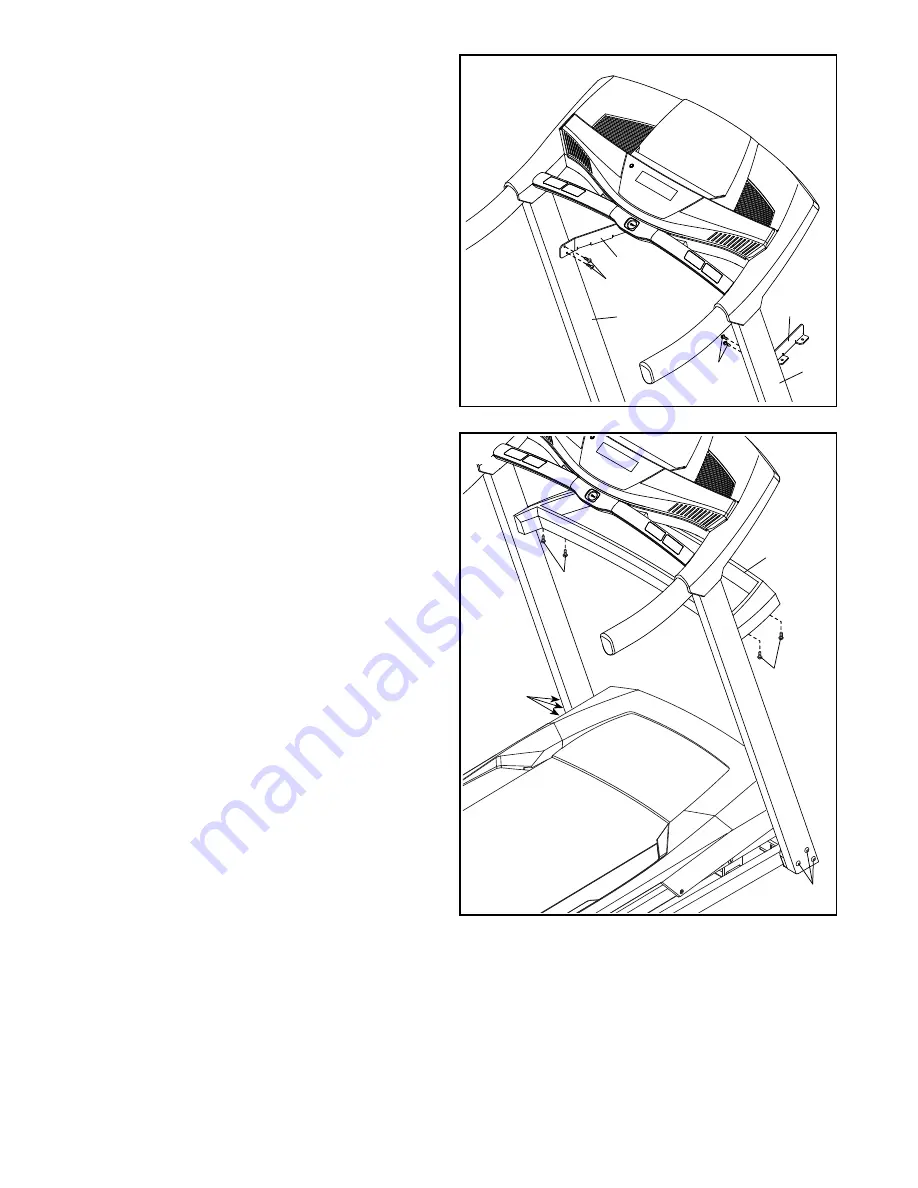
12. Attach the Tray (86) with four #8 x 3/4" Screws 

(4). 

Start all four Screws, and then tighten 

them.

  Tighten the six 3/8" x 3 1/4" Screws (2).

4

86

4

2

2

12

Содержание 525 ZLT

Страница 1: ...l for future reference USER S MANUAL www iconeurope com CUSTOMER SERVICE UNITED KINGDOM Call 08457 089 009 From Ireland 053 92 36102 Website www iconsupport eu E mail csuk iconeurope com Write ICON He...

Страница 2: ...e The decals may not be shown at actual size 305284 WARNING DECAL PLACEMENT 2 IMPORTANT PRECAUTIONS 3 BEFORE YOU BEGIN 5 PART IDENTIFICATION CHART 6 ASSEMBLY 7 HOW TO USE THE TREADMILL 15 HOW TO FOLD...

Страница 3: ...r appliance should be on the same circuit When replacing the fuse in the power cord adapter insert an ASTA approved BS1362 13 amp fuse into the fuse carrier 13 If an extension cord is needed use only...

Страница 4: ...opening on the treadmill 25 Inspect and properly tighten all parts of the treadmill regularly 26 DANGER Always unplug the power cord immediately after use before clean ing the treadmill and before pe...

Страница 5: ...of this manual To help us assist you note the product model number and serial number before contacting us The model number and the location of the serial number decal are shown on the front cover of t...

Страница 6: ...1 M8 x 53mm Bolt 56 1 M8 Nut 67 2 PART IDENTIFICATION CHART Use the drawings below to identify small parts used for assembly The number in parentheses below each draw ing is the key number of the part...

Страница 7: ...Base Remove the tie securing the Upright Wire 63 Press a Base Cap 70 into each side of the Base 74 only one side is shown 1 2 B A 74 Assembly requires two persons Place all parts in a cleared area an...

Страница 8: ...Then insert the Upright Wire into the lower end of the Right Upright as you pull the other end of the wire tie out of the Right Upright 4 Lay the Right Upright 76 near the Base 74 as shown Attach the...

Страница 9: ...lly tighten the Screws yet Attach the Left Upright not shown in the same way Note There are no wires on the left side 3 76 3 2 74 63 5 6 Identify the Left and Right Handrails 59 64 Note The Right Hand...

Страница 10: ...l four Screws and then tighten them Tighten the four 1 4 x 1 1 4 Screws 77 7 8 With the help of a second person hold the con sole assembly near the Right Handrail 64 See the inset drawing Connect the...

Страница 11: ...the Right Handrail 64 through the indicated hole as you set the console assembly on the Uprights 66 76 Make sure that no wires are pinched Attach the console assembly with six 8 x 3 4 Screws 4 Start a...

Страница 12: ...ht Tray Brackets 83 84 to the Uprights 66 76 with four 8 x 3 4 Screws 4 84 4 4 66 83 76 12 Attach the Tray 86 with four 8 x 3 4 Screws 4 Start all four Screws and then tighten them Tighten the six 3 8...

Страница 13: ...8 with two 1 4 x 1 3 4 Screws 8 8 82 38 8 14 Orient the Storage Latch 68 so that the decals are facing away from the treadmill as shown Attach the lower end of the Storage Latch 68 to the bracket on t...

Страница 14: ...ge to the console keep the treadmill out of direct sunlight Keep the included hex keys in a secure place one of the hex keys is used to adjust the walking belt see pages 23 and 24 Note Extra hardware...

Страница 15: ...power cord into the socket on the treadmill 2 Plug the power cord into an appropriate outlet that is properly installed and earthed in accordance with all local codes and ordinances DANGER Improper co...

Страница 16: ...can even listen to your favorite workout music or audio books with the console s sound system while you exercise To turn on the power see page 17 To use the man ual mode see page 17 To use a preset w...

Страница 17: ...est the clip by carefully taking a few steps backward if the key is not pulled from the console adjust the position of the clip HOW TO USE THE MANUAL MODE 1 Insert the key into the console See HOW TO...

Страница 18: ...step 6 The upper display can show the elapsed time the distance that you have walked or run the approximate number of calories you have burned or the speed of the walking belt Press the Priority Disp...

Страница 19: ...r the current segment At the end of each segment a series of tones will sound and the next segment of the profile will begin to flash If a different speed and or incline setting is programmed for the...

Страница 20: ...e will function normally when you plug in the power cord press the power switch into the reset position and insert the key into the console However when you remove the key the displays will remain lit...

Страница 21: ...ge position in temperatures above 85 F 30 C HOW TO MOVE THE TREADMILL Before moving the treadmill fold it as described at the left CAUTION Make sure that the latch knob is locked in the storage positi...

Страница 22: ...d in make sure that the key is inserted into the console c Check the power switch located on the treadmill frame near the power cord If the switch protrudes as shown the switch has tripped To reset th...

Страница 23: ...return to the minimum level This will recalibrate the incline system If the incline system does not begin calibrating press the Stop button again and then press the Incline increase or decrease button...

Страница 24: ...ot to overtighten the walking belt Then plug in the power cord insert the key and run the treadmill for a few minutes Repeat until the walking belt is centered SYMPTOM The walking belt slips when walk...

Страница 25: ...c Exercise If your goal is to strengthen your cardiovascular system you must perform aerobic exercise which is activity that requires large amounts of oxygen for prolonged periods of time For aerobic...

Страница 26: ...lles Stretch With one leg in front of the other reach forward and place your hands against a wall Keep your back leg straight and your back foot flat on the floor Bend your front leg lean forward and...

Страница 27: ...r Belt 46 1 Right Rear Foot 47 8 10 Flat Washer 48 1 Motor Hood 49 1 Incline Motor 50 2 Lift Frame Bushing 51 1 Lift Frame 52 1 Belly Pan 53 1 Receptacle 54 1 Power Cord 55 1 Power Switch 56 1 M8 x 53...

Страница 28: ...8 28 28 14 14 14 11 14 14 14 43 46 11 42 35 65 65 25 25 19 19 38 24 24 20 20 1 1 1 45 23 23 23 23 23 23 23 23 47 47 47 47 47 47 47 47 34 28 34 34 5 5 5 5 8 8 82 85 17 87 36 4 37 81 1 22 1 1 88 14 89 9...

Страница 29: ...29 52 4 4 48 13 51 32 15 16 16 49 4 4 4 4 26 10 26 50 50 13 13 4 4 10 4 4 53 55 54 EXPLODED DRAWING B Model No PETL59714 0 R0114A...

Страница 30: ...71 34 71 10 9 75 72 34 70 70 2 3 2 3 3 2 59 63 63 73 64 60 60 1 70 12 12 4 21 44 76 73 69 69 78 6 77 78 77 86 4 4 84 83 4 4 61 6 61 33 67 68 67 56 9 72 34 10 75 70 EXPLODED DRAWING C Model No PETL597...

Страница 31: ...31 62 58 57 4 4 4 4 4 4 4 4 4 4 4 4 4 4 4 4 4 80 7 79 EXPLODED DRAWING D Model No PETL59714 0 R0114A...

Страница 32: ...require more information about safe and correct disposal methods please contact your local city office or the establishment where you purchased this product RECYCLING INFORMATION To order replacement...

Отзывы: