


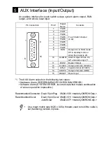


This is GP’s serial port for RS-232C and RS-422 interface. Connect GP’s
host here.
3
Serial Interface
*
Pin # 14 can be used for the power supply for the user's optional equipment
connected to the GP.
Recommended Connector: Dsub 25 pin plug
XM2A-2501 <made by OMRON Corp.>
Recommended Cover:
Dsub 25 pin Cover XM2S-2511 <made by OMRON Corp.>
Jack Screw
XM2Z-0071 <made by OMRON Corp.>
•
Use rough metric type M2.6 x 0.45p threads used to hold the cable’s
set (fastening) screws in place.
Recommended Cable:
CO-MA-VV-SB5P x 28AWG <made by HITACHI Cable Ltd.>
•
Since Pin#14(VCC)is unprotected, be sure to keep the output current
in the rated range.
•
Be sure to connect this unit's SG/GND (Signal Ground) terminal to the other
unit's Signal Ground terminal..
Pin
#
Signal
Name
Condition
Pin
#
Signal
Name
Condition
1
FG
Frame ground
14
VCC
5V
±
5% output
0.25A *
2
SD
Send data
(RS-232C)
15
SDB
Send data B
(RS-422)
3
RD
Receive data
(RS-232C)
16
RDB
Receive data B
(RS-422)
4
RS
Request send
(RS-232C)
17
NC
No connection
5
CS
Clear send
(RS-232C)
18
CSB
Clear send B
(RS-422)
6
NC
No connection
19
ERB
Enable receive B
(RS-422)
7
GND
Signal ground
20
ER
Enable receive
(RS-232C)
8
CD
Carrier detect
(RS-232C)
21
CSA
Clear send A
(RS-422)
9
TRMX
Termination
(RS-422)
22
ERA
Enable receive A
(RS-422)
10
RDA
Receive data A
(RS-422)
23
RESERVED
Reserved for future
use
11
SDA
Send data A
(RS-422)
24
NC
No connection
12
NC
No connection
25
RESERVED
Reserved for future
use
13
NC
No connection
1
13
14
25


