Assembly Instructions
Masking System
Cinomask F-100
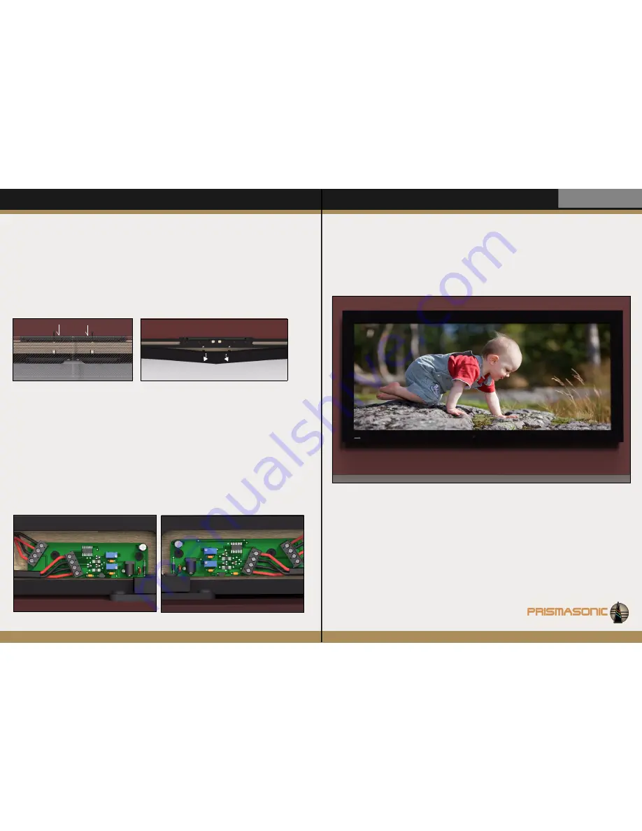
You are done!
Enjoy your new 2.40:1 setup. In the use, the aspect ratios between the
terminal stops are adjusted simply by releasing the control button to match the
aspect ratio of each media.
----------------------------------------------------------------------------------------------
STEP 13
Exactly similarly attach the right side velvet frames to framework. The elastic joint of left and right horizontal
frames have been designed to be tight. After matching the frame ends by hand (
as instructed in a
tip
below)
, the
parallel positions with each other can be fine tuned by the two
Cap Screw
s
m5 x 30 (Fig 13a)
, which are pushing
the both frame ends
upwards
. Finally attach the lower horizontal frames to their places. Still remove the cover
sheet from the circular IR window of left bottom frame. The screen with the masking system is now ready for the
use.
TIP!
A tight center joint of horizontal frames can be connected together without difficulty by pulling the both center
ends away from framework bars until they match to each other, after which they can be released to go back down
against the framework
(Fig 13b)
. Before doing this the both frames must have been attached from center to the
framework bars
(Fig 12b)
.
Fig 13
a)
b)
Top view
STEP 14
Now power the system up from either left or right side motor control board
(Fig 8b
and
Fig 14).
By pressing and
holding the
‘OPEN’
button of remote controller, drive the masks to full open (2.40:1) position. The opto electrical
sensors stop the masks automatically after they disappear under the main velvet frames. After this drive the masks
to full close (1.33:1) position, where they again automatically stop. If the side mask travels from
open to close
are
not quite synchronous to each other, their speed can be further adjusted. This is done with
Screw Driver
by
opening (~
5-10 rounds to
counter clock wise
) the trimmer screw of motor control board marked by
a)
in
Fig 14,
but only at the
side which was moving slower
. The iterative tuning back and forth can be performed to find the
perfect synchrony.
Similarly the calibration can be done to the
close to open
movement. Now, however, the trimmer screw marked
by
b)
in
Fig 14
is closed (~
3-5 rounds to
clock wise
)
at the
side which was moving faster.
And again the iterative
tuning back and forth can be operated to find the synchrony.
NOTE!
The system is good to be powered down while adjusting the trimmer screws with screw driver
a)
b)
left side board
Fig 14
a)
b)
right side board
Masks have been driven to full open 2.40:1 position


