Page 4
PNET Opto-Input – Quick Start Guide
The other Switch Setting of interest is Switch #8 which selects the LED mode
for the Trigger Indicators E1, E2, E3, and E4. When switch #8 is off, the E1-E4
indicators will display when the Local Trigger Input chan is triggered. This can
be very helpful for diagnosing wiring problems or seeing when trigger sources
are active. When switch #8 is ON, the indicators will light when ANY PNET
Trigger Source with the same slot number is sending out a trigger event on the
PNET. This can be helpful in monitoring all the trigger messages on the PNET.
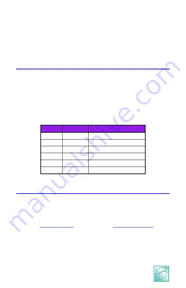
5 Connect the PNET Cable
The PNET Jacks are both the same, giving you the flexibility to ‘loop’ through
and connect many devices to the PNET network. The cables are 6-wire Modular
cables and can be flat or twisted pairs. PNET cables include 12VDC power that
comes in very handy for the PNET Opto-Input as the 12VDC on the cable can
power many of these boards. PNET Cables should be wired as “Straight
Through” and not “flip” anywhere along the path. Nothing will be damaged if a
cable is reversed, but the PNET Communications Data lines would be reversed
making PNET malfunction. PNET cables can be plugged or un-plugged with the
power on.
Pin
Name
Description
1
+12VDC PNET Power Supply
2
GND
PNET Signal Ground
3
PNET
Communications Data
4
PNET
Communications Data
5
GND
PNET Signal Ground
6
+12VDC PNET Power Supply
Figure 4 - PNET Jack Pinout
6 Test Your New Module
With the power applied through the PNET cable, you should see the Green LED
light showing a functional board. The Red LED will show anytime this board
sends data on the PNET, or if this board receives any data.
If you have any further questions you can consult the full length manual from
our websitsome fun Layout Lighting and Dream Player applications.


