background image

CONTROLS AND INSTRUMENTS     4-15 


PA1633 X3-45 Commuter Operator’s Manual 

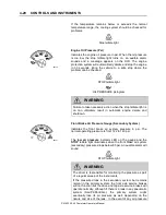
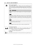
AIR VENTS 


Three adjustable driver air vents in 
the dashboard and one near the 
door feed air to the driver's 
compartment. Use the HVAC 
control panel to set air temperature 
and fan speed. 

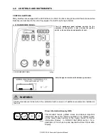
ELECTRONIC DESTINATION SIGN 

The electronic Destination Sign System (DSS) is 
automatically activated when the ignition switch is 
turned to the ON position. 

The destination sign database is programmed 
with a computer via “Data Transit Software” and 
then transferred in the central control unit. 

Each message is assigned a code that the 
operator can enter on the OSCP (Operator’s 
System Control Panel) for the related info to be 
displayed. 


DESTINATION SIGN CENTRAL CONTROL UNIT ICON 

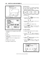
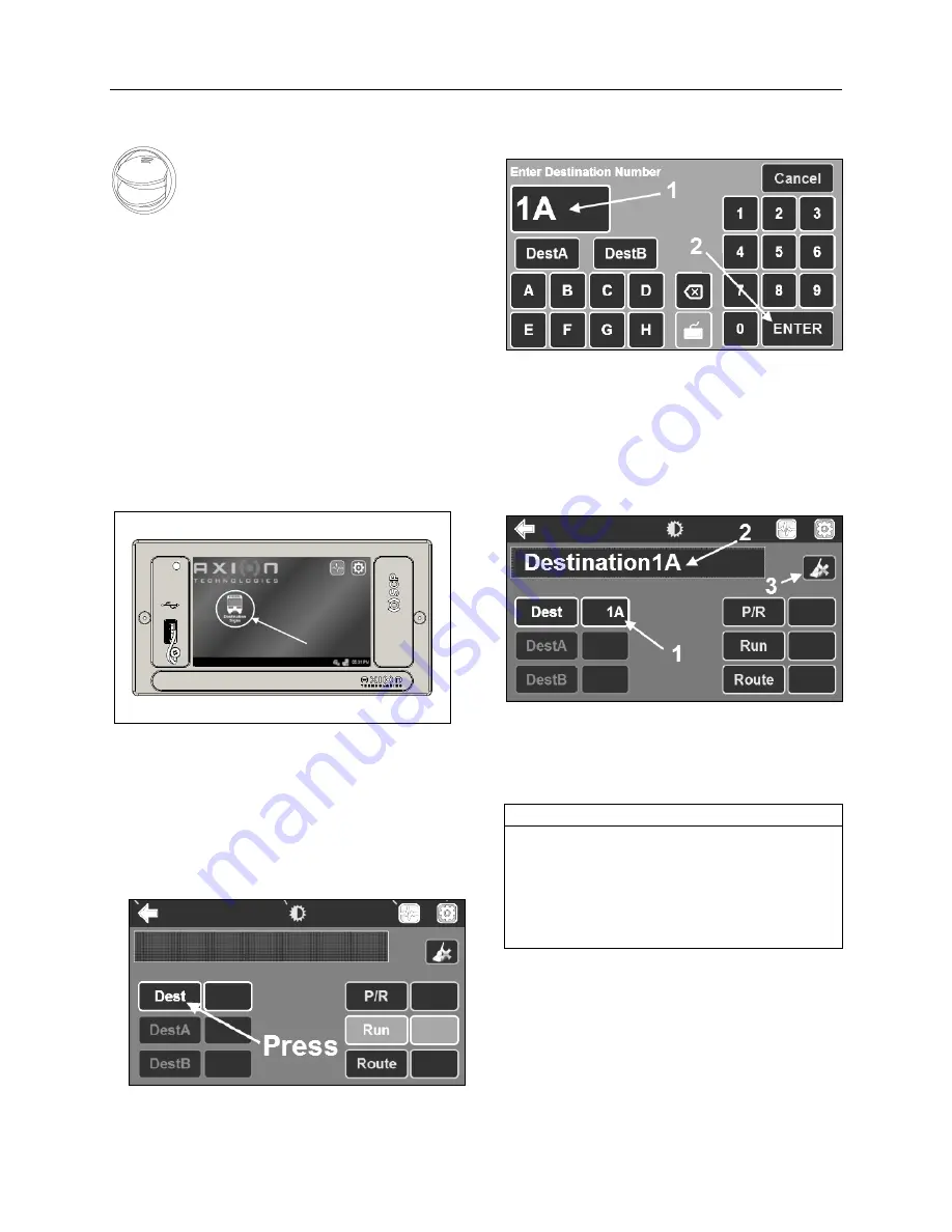
To enter a destination

  Consult your Transit Authority code list. 

  Press the destination sign icon on the main 

screen to access the destination sign OSCP 
menu. 

  Press the <Dest> button.   


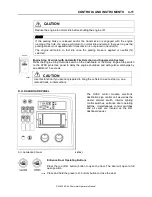
DESTINATION SIGN OSCP MENU 

  Using the alphanumeric keyboard enter 

the 

code

 for the destination to be displayed (1). 

  Press <ENTER> to validate your choice (2). 


DESTINATION SIGN ALPHANUMERIC KEYBOARD 

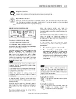
When the destination code  is entered, OSCP 
displays the following information: 

  Destination number displays in the Dest  field 

(1). 

  Front destination content (message) is 

displayed in the text field (2). 


OSCP MESSAGE AND NUMBER 


Use the ERASE key at the top right of the 
screen to delete or cancel the last entry on the 
control unit (3). 

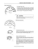
NOTE 

<DestA> and <DestB> buttons can be used to 
store two destination numbers. 

When a destination number is entered in the 
Dest field, press <DestA> or <DestB> to store 
your choice, press again to recall the 
associated destination number.


To enter a route number: 

Содержание X3-45 COMMUTER 2018

Страница 1: ...OPERATOR S MANUAL X3 45 COMMUTER COACH...

Страница 2: ......

Страница 3: ...COACH MANUFACTURER X3 45 COMMUTER OPERATING MANUAL March 2018...

Страница 4: ...PA1633 MARCH 2018 Featuring REVISION DESCRIPTION DATE FIRST RELEASE 03 2018...

Страница 5: ...eep this manual in the coach at all times Make sure this manual is kept with the coach when ownership is transferred Please use the appropriate card at the end of this manual to promptly notify Prevos...

Страница 6: ...led on this vehicle at the factory were certified to the U S EPA Greenhouse Gas GHG and National Highway Traffic Safety Administration NHTSA Fuel Efficiency regulations Replacement of these tires shou...

Страница 7: ...10 SECTION 11 SECTION 12 SAFETY PRECAUTIONS 1 1 COACH EXTERIOR 2 1 COACH INTERIOR 3 1 CONTROLS AND INSTRUMENTS 4 1 OTHER FEATURES 5 1 STARTING AND STOPPING PROCEDURE 6 1 SAFETY FEATURES AND EQUIPMENT...

Страница 8: ......

Страница 9: ...SAFETY PRECAUTIONS 1 1 PA1633 X3 45 Commuter Operator s Manual SECTION 1 SAFETY PRECAUTIONS SAFE OPERATING PRACTICES 2 DEFENSIVE DRIVING PRACTICES 2 OTHER PRECAUTIONS 3...

Страница 10: ...hicle Shut off the engine before refueling adding oil performing maintenance or servicing tasks unless stated otherwise Fuel is highly flammable and explosive Do not smoke when refueling Keep away fro...

Страница 11: ...SITION 65 Diesel engine exhaust and some of its constituents are known to the State of California to cause cancer birth defects and other reproductive harm Battery posts terminals and other related ac...

Страница 12: ......

Страница 13: ...ERTREATMENT SYSTEM ACCESS DOOR 5 ENGINE RADIATOR DOOR 6 SCR CONVERTER ACCESS DOOR 6 CONDENSER COMPARTMENT A C 7 EVAPORATOR COMPARTMENT 8 COOLANT HEATER COMPARTMENT 9 REAR FENDERS 9 FRONT ELECTRICAL AN...

Страница 14: ...ir access door 8 Baggage compartment 9 Entrance door control switch 10 Bi fold entrance door 11 Electronic destination sign or route number 12 Exhaust aftertreatment system access door 13 Engine compa...

Страница 15: ...ss 5 Power steering fluid reservoir 6 Engine oil dipstick 7 Air filter 8 Air filter restriction sensor 9 Alternator Road side 10 Alternators Curb side 11 Engine oil filler tube 12 Central A C compress...

Страница 16: ...ck heater 120 volts connector ENGINE COMPARTMENT CURB SIDE DOOR This door can be locked or unlocked using the square drive T key ENGINE COMPARTMENT R H SIDE 18607_1 A telltale light illuminates when o...

Страница 17: ...mission fluid dipstick NOTE The engine compartment lights will turn on automatically when the engine door is opened Check the engine compartment lamps swith on the right top corner if no light A catch...

Страница 18: ...te at any moment Keep hands away from cooling fans or keep the radiator door closed WARNING Cooling fans may be running when the engine is shut down in the following conditions If a High Exhaust Tempe...

Страница 19: ...eatment System to cool before handling Wear protective clothing and glove while servicing CONDENSER COMPARTMENT A C Open the fuel filler neck access hatch and push the lever down to unlatch the conden...

Страница 20: ...partment located to its left Pull the release latch then slide your hand in the opening to depress the evaporator compartment door secondary lock and swing open OPENING THE EVAPORATOR COMPARTMENT DOOR...

Страница 21: ...ar fender COOLANT HEATER COMPARTMENT REAR FENDERS Rear fenders are hinged for maintenance on brakes and suspension Each rear fender panel has two mechanical spring loaded holding devices fixing it to...

Страница 22: ...compartment turns ON automatically when the door is opened FRONT SERVICE COMPARTMENT 18611 BAGGAGE COMPARTMENTS The compartments can be locked or unlocked by using the provided key The baggage compar...

Страница 23: ...is approximately 95 full CAUTION Diesel exhaust fluid DEF will begin to crystallize and freeze at 12 F 11 C and expand by 7 when frozen To allow expansion without damaging the DEF tank do not fill the...

Страница 24: ...ACCESS DOORS Refer to Other Features for more information on operating the wheelchair lift REAR VIEW MIRRORS The vehicle is equipped with flat type and convex type rear view mirrors Convex mirrors gi...

Страница 25: ...r Lock Mode 4 SEAT RECONFIGURATION FOR MOBILITY DEVICES 5 SEATED to STOWED position 5 STOWED to SEATED position 6 4 POINT SECUREMENT WITH ANCHORAGE TO PASSENGERS SEAT PEDESTALS 7 Wheelchair Occupant R...

Страница 26: ...around the driver s area Three are located on the dashboard two on the R H side and one on the L H refer to Controls Instruments section Another one is located close to the door below the modesty pane...

Страница 27: ...t operation becomes defective report to maintenance personnel immediately FASTENING SEATBELT 18028 NOTE The safety belt must be pulled out slowly and continuously otherwise it will lock the reel befor...

Страница 28: ...receptacle Fold up armrests are installed on the seat PASSENGER SEAT BELTS Passengers are strongly advised to wear seat belts at all times Children can use a passenger seat belt as long as they are l...

Страница 29: ...e child safety seat not being properly secured When using a booster seat do not pull the shoulder belt all the way out Doing so would engage the ALR lock mode which is not recommended with booster sea...

Страница 30: ...l down in the green zone With your feet depress both levers located under the seat STOWED to SEATED position With your feet lift both levers located under the seat With your foot depress the pedal in...

Страница 31: ...curement system includes 4 wheelchair restraint belts and retractors with anchorage to passengers seat pedestals Occupant securements lap and shoulder belt WHEELCHAIR AND OCCUPANT RESTRAINT SYSTEM To...

Страница 32: ...button on the lap belt buckle Use the blue webbing loops whenever the wheelchair restraint belt hook cannot reach a stiff member of the wheelchair chassis TYPICAL USE OF THE BLUE WEBBING LOOPS OVERHEA...

Страница 33: ...e vehicle helping reduce vibration and noise Fixed windows cannot be opened Emergency Windows These windows can be opened from inside the vehicle as emergency exits A riveted tag on window sills indic...

Страница 34: ...traveling under overpasses with the ventilation hatch es open Check for maximum clearance height OVERHEAD COMPARTMENTS Passenger carry on baggage is stored in overhead compartments on each side of the...

Страница 35: ...TROL SWITCHES 8 L H DASHBOARD PANEL 8 R H DASHBOARD PANEL 11 DRIVER S HVAC CONTROL UNIT 13 Passenger s section temperature setting 14 AIR VENTS 15 ELECTRONIC DESTINATION SIGN 15 INSTRUMENT CLUSTER 18...

Страница 36: ...3 45 Commuter Operator s Manual ACCELERATOR PEDAL 33 ALLISON AUTOMATIC TRANSMISSION 33 OPERATION 33 PUSHBUTTON SHIFT SELECTOR 33 PRIMARY AND SECONDARY SHIFT MODES 34 DESCRIPTION OF AVAILABLE RANGES 34...

Страница 37: ...of an ignition key Use the ignition lever to activate the electrical circuit by turning it to the ON position IGNITION SWITCH POSITIONS 06354 For further details refer to STARTING AND STOPPING PROCEDU...

Страница 38: ...ENTS PA1633 X3 45 Commuter Operator s Manual DRIVER S SECTION 18671_3 1 Lateral control panel 2 DOT certification plate 3 Diagnostic tool receptacle OBD 4 Foot operated steering wheel adjustment unloc...

Страница 39: ...ransmission in this section for operating instructions and more information CONTROL SWITCHES 2 Back Up Alarm Cancel Switch 06338 Use this rocker switch to cancel the back up alarm NOTE Normal operatio...

Страница 40: ...e right side control MIRROR CONTROLS 06374_1 PARKING BRAKES CONTROL VALVE 4 Spring loaded parking brakes are applied by pulling up the control valve knob Push down to release brakes Refer to SAFETY FE...

Страница 41: ...Information Display DID Keyboard 3 Instrument Cluster 4 Vehicle Clearance Information 5 R H Dashboard Panel 6 HVAC Control Unit 7 Electronic Destination Sign Central Control Unit 8 Air Vents 9 Bright...

Страница 42: ...on switch radio control and an adjustable air vent L H DASHBOARD PANEL 06762_1 Vehicle height information with hatches up and down WARNING Vehicle clearance is higher when the ventilation hatch is ope...

Страница 43: ...switch is fully depressed second position 06268 Wheelchair Lift Power Switch Activate the optional wheelchair lift by pressing down on the rocker switch Refer to OTHER FEATURES section and to wheelcha...

Страница 44: ...e TCS ESC telltale blinks slowly when the TCS Mud Snow mode is active Always remember to turn the Mud Snow feature off when driving on a firm road surface A new ignition cycle or a second pressing of...

Страница 45: ...verride switch on the dashboard or the Delay Engine Stop switch on the AFSS protection panel to delay the engine shutdown and extinguisher discharge by an additional 15 seconds CAUTION Use this functi...

Страница 46: ...s This switch powers the reading light circuit enabling passengers to operate their personal reading lights Refer to VEHICLE INTERIOR section CAUTION To avoid running down the batteries when the engin...

Страница 47: ...vent cooling loss To prevent battery run down the central HVAC unit will not operate if the charging system is not working properly When the HVAC system is in operation park at least 4 feet from other...

Страница 48: ...press on the or the sign Pressing these buttons will flash the displayed set point and the word SET will highlight Temperature range is between 60 F and 82 F 16 C to 28 C In case of interior temperat...

Страница 49: ...r a destination Consult your Transit Authority code list Press the destination sign icon on the main screen to access the destination sign OSCP menu Press the Dest button DESTINATION SIGN OSCP MENU Us...

Страница 50: ...YBOARD When the route number is entered OSCP displays the following information Destination number displays in the Dest field 1 Route number displays in the Route field 2 Route number and front destin...

Страница 51: ...he floor just in front of the driver seat When activated a warning message will be displayed on all exterior destination signs to prompt passer by to call for help on behalf of the operator and allow...

Страница 52: ...e telltale lights and the Driver Information Display DID Indications and warnings are presented according to three levels of attention required 1 The Telltale Lights The highest level of attention The...

Страница 53: ...Turbo boost pressure psi Indicates the turbo boost pressure in psi This pressure should be the same at a given engine temperature speed and load An unusual reading could indicate an engine failure 06...

Страница 54: ...c engine derate and shutdown 06737 Front Brake Air Pressure Gauge Secondary System Indicates the front brake air system pressure in psi The normal operating pressure is from 122 to 140 psi The low air...

Страница 55: ...ent of a pressure loss in the primary brake system the drive and tag axle service brakes will not function normally It is critical to bring the coach to a safe stop as quickly as possible If there is...

Страница 56: ...is only 24 gallons 92 liters left in the fuel tank TELLTALE LIGHTS The telltale lights illuminate during 5 seconds at the start of every ignition cycle as a light bulb check Stop Indicates that a ser...

Страница 57: ...tral below 3 mph 5 km h Aftertreatment System Malfunction Malfunction Indicator Lamp Indicates a failure of an emission control device May illuminates at the same time as the CHECK amber warning light...

Страница 58: ...ved Intake Air Preheater On Wait Before Starting Illuminates when the intake air preheater element is in function Wait until this telltale light has turned off before starting the engine For more info...

Страница 59: ...CK Telltale Light This telltale light means that a fault or an abnormal operating condition has been detected The vehicle must be checked at the next stop If the CHECK telltale light illuminates an as...

Страница 60: ...isplay DID keyboard to scroll through them To select a menu 1 Press the or button to display the list of available menus 2 Use the button to scroll up or down through the menus 3 Use the button to ope...

Страница 61: ...Pictogram Description Date and time Outside air temperature Icing condition If the exterior temperature is between 32 to 35 f the outside air temperature pictogram described above is replaced by this...

Страница 62: ...essure Low accessories air pressure Low air in interlock brake system Normal pressure should be between 122 and 144 psi A C Fail Wait to start This pictogram illuminate at any instance of starter lock...

Страница 63: ...front suspension of the vehicle kneeling is lowered Cooling fans low voltage This pictogram indicates that battery voltage is too low for proper fan operation TCS Status Icon This pictogram indicates...

Страница 64: ...icle Cycle the ignition between the ON and OFF position and then start the vehicle normally This can be done on a temporary basis when a false alarm is activated by a defective fire detector The drive...

Страница 65: ...een initiated manually Entrance door interlock Confirms that the entrance door interlock is enabled Entrance door interlock disabled Indicates that the entrance door interlock is disabled through the...

Страница 66: ...s the foot operated switch to activate the electric horn city horn DISTRESS SIGNAL SWITCH Press the foot operated distress signal switch to signal an emergency and ask for immediate assistance A warni...

Страница 67: ...nstructions and driving tips in the Allison 5 th Generation Bus Series Operator s Manual included in your vehicle s publication box OPERATION When a button is depressed on the transmission control pad...

Страница 68: ...lied The pushbutton shift selector automatically select N Neutral when the ignition switch is turned ON NOTE The automatic transmission does not have a park P position Select N Neutral and apply parki...

Страница 69: ...hen slowing the transmission will automatically downshift to first range Low ranges provide progressively greater engine and retarder braking power the lower the range the greater the engine and retar...

Страница 70: ...4 36 CONTROLS AND INSTRUMENTS PA1633 X3 45 Commuter Operator s Manual...

Страница 71: ...INFORMATION DISPLAY DID MENUS 9 GAUGES 10 FUEL DATA 11 TIME DISTANCE 12 VEHICLE MESSAGES 13 RESET TRIP DATA 13 DISPLAY SETTINGS 13 DIAGNOSTICS 15 PRE TRIP ASSISTANT OPTION 17 DATA LOG 18 AFTERTREATMEN...

Страница 72: ...Beam 33 Adjust Acoustic Sensor Timing 33 INTERIOR APPOINTMENTS 33 Wheelchair Restraint System 34 Wheelchair Occupant Restraint 34 EMERGENCY OPERATION 34 Wheelchair area sliding door emergency unlock...

Страница 73: ...dized due to the heat generated by the engine internal combustion process During normal highway operation exhaust temperatures alone are usually high enough to oxidize accumulating soot In low ambient...

Страница 74: ...the CHECK telltale light will illuminate In that situation engine performance is limited Perform a parked regeneration IMMEDIATELY to avoid further derate and prevent from entering into Level 4 LEVEL...

Страница 75: ...on is required immediately If stationary regeneration is still not performed engine power derate and shutdown sequence may occur as per level 1 to level 4 sequence To initiate a stationary regeneratio...

Страница 76: ...lt diesel exhaust fluid DEF If urea solution comes into contact with the skin rinse with plenty of water and remove contaminated clothing If urea solution comes into contact with the eyes rinse for se...

Страница 77: ...DEF QUALITY DRIVER WARNINGS AND INDUCEMENTS Conditions Triggers Amber Warning Light Did Message And Audible Warning Inducement 1 Good DEF quality None None 2 Poor DEF quality detected solid 1 4 DEF QU...

Страница 78: ...2 4 SRC SYSTEM OK TO CONTINUE DRIVING 3 cycles of 2 beeps Engine torque derated 25 40 Engine torque reduction in 240 minutes 5 An SCR fault has been detected solid 3 4 SCR SYSTEM 5 MPH LIMIT IF VEHICL...

Страница 79: ...essure 8 Battery Voltage 9 Allison Transmission Oil Life 10 Battery State Of Charge 11 Electric Cooling Fan Status Display Settings 1 Language 2 Units 3 Time Date 4 Favorite Display Setting 5 Display...

Страница 80: ...s in the vehicle Current Gear Position I Shift transmission only Indicates the current gear position selected on the I Shift transmission D drive N neutral R reverse M manual 1 Outside Temperature 2 E...

Страница 81: ...both Charge Air Cooler and radiator cooling fans expressed in percentage from 0 to 100 FUEL DATA The Fuel Data menu provides information on the fuel consumption of the vehicle in various situations Fo...

Страница 82: ...me of arrival ETA 1 Time And Date Adjust time and date with this menu The instrument cluster has its own internal battery so the date and date setting is keep in memory even if the vehicle s battery i...

Страница 83: ...t will illuminate Scroll through the messages using the up down button Press ESC button to return to main menu RESET TRIP DATA When the Reset Trip Data menu is open pressing and holding down the ENTER...

Страница 84: ...utton until Gauge 1 position is selected Press ENTER button to confirm Use UP DOWN button to scroll through the available gauges When the engine oil temperature gauge is displayed press ENTER button t...

Страница 85: ...on the control units in the vehicle to check for faults Instrument tests are available to check the telltales gauges display and speaker The part number of a control unit can be identified in the par...

Страница 86: ...Use this menu to delete an inactive fault for a particular control unit Note it is not possible to delete inactive faults of the Engine ECU 6 Vehicle Tests Use this menu to perform tests on several c...

Страница 87: ...to end the test and turn off all the exterior lights 2 Air leakage Monitor The Air Leakage check allows the driver to accurately measure the amount of air pressure drop in the front and rear brake air...

Страница 88: ...ECU Available information Total distance traveled Total fuel used Total engine hours Total idle time Total PTO hours Total engine revolutions 3 Trip Data This menu displays the trip information listed...

Страница 89: ...This menu can only be accessed if the correct password has been entered Use this function to reset measurements of the Trip Data menu before each new trip or leg AFTERTREATMENT This menu permits to t...

Страница 90: ...n menu you can cancel a REGEN cycle PASSWORD Certain functions are password protected These passwords give the user access to all password protected functions The default password is 0000 1 1 Password...

Страница 91: ...et operator The driver can send and receive short text messages which are visible through the Driver Information Display The following menus are available 1 Read Message Quick Response only available...

Страница 92: ...tion is the normal operational mode of the system SELF DIAGNOSTIC MODE The self diagnostic mode is entered through a menu selection using the LCD The self diagnostic includes the following tests Gauge...

Страница 93: ...Alert CHECK COOL TEMP Yes No DM1 Clears Low Coolant Level LOW COOLANT LEVEL Yes No message clears after 30 sec LOW COOLANT LEVEL Yes No Flag Clears Check Coolant SNS CHECK COOLANT SNS Yes No Flag Cle...

Страница 94: ...llowing screen that is used to select if values are to be displayed in metric units or English units Pressing M or waiting 5 seconds exits to Settings and Diagnostics menu 2 Contrast Selecting menu it...

Страница 95: ...Number SPN and Failure mode Identifier FMI as received from the engine for active faults via J1939 5 Trans Faults For all ECU an array is defined containing DTC SPN Specific FMI If the SPN is not kno...

Страница 96: ...The main use for these screens is in troubleshooting the system 8 Brake Lining state Item 15 A sub menu is displayed to choose between 3 types of displaying In 1 32 of inches In millimeters In The dis...

Страница 97: ...vehicle to a complete stop NOTE Extended use of transmission output retarder will raise the temperature of the transmission fluid A disable switch is located in the RJB close to the master brake inter...

Страница 98: ...er obstacles which could damage the coach during kneeling NOTE Kneeling is disabled when the entrance door is open NOTE The kneeling system does not operate when the coach is traveling over 5 mph 8 km...

Страница 99: ...r If the parking brake is not activated a switch in the door will activate the parking brake when it detects the door is open The wheelchair area door is fitted with an electric lock and will unlock w...

Страница 100: ...tain there are no obstacles beneath platform Open lift access door completely LIFT ACCESS DOOR OPEN The vehicle and lift are equipped with a safety interlock system i e transmission into neutral parki...

Страница 101: ...l to platform Repeat for right handrail Buckle safety belt 12 STOW PLATFORM Press and hold STOW button Close wheelchair area door at intermediate height Press and hold STOW button until platform reach...

Страница 102: ...e wheelchair fits safely on the platform Keep arms and legs away from moving parts NOTE The indicator light on the control device illuminates when power is supplied when the lift electrical circuit is...

Страница 103: ...ash turn sensor adjustment screw slightly counterclockwise NOTE If an adjustment is made repeat the previous step where wheelchair is between 18 and 24 inches from doorway Adjust Acoustic Sensor Timin...

Страница 104: ...lack lap belt and a black shoulder belt with a tongue that attaches on the lap belt stud Refer to the information on the actual seats for detailed proper securement instructions Instructions labels an...

Страница 105: ...pump handle from inside the lift mechanism access door 3 Turn the manual platform release shafts using pump handle extension to disengage the platform and then lift the stowlock mechanical catch 4 Gr...

Страница 106: ...lease valve actuating rod back DOWN until lightly snug 5 Using the rollstop manual control knob OPEN the rollstop Pull rollstop control knob out and rotate fully counterclockwise Rollstop must lie fla...

Страница 107: ...urpose of the directional placement is to make the bike nearest the bus easier to unload 5 Raise the Support Arm over the front tire The Support Arm s number one purpose is to add lateral support for...

Страница 108: ...5 38 OTHER FEATURES PA1633 X3 45 Commuter Operator s Manual...

Страница 109: ...GNITION SWITCH 2 STARTING THE ENGINE 2 STARTING FROM THE DRIVER S SEAT 2 Stopping the Engine 3 STARTING FROM THE ENGINE COMPARTMENT 4 Stopping the Engine 4 COLD WEATHER STARTING 4 JUMP STARTING 5 ENGI...

Страница 110: ...e place The electrical circuits are not activated when the switch is in this position Only the accessories connected directly to the batteries can be activated Maintain the switch in this position whe...

Страница 111: ...pedal before starting This could result in an electronic control unit fault and degrade the fuel system control CAUTION Special precautions are necessary with turbocharged engines to avoid possible tu...

Страница 112: ...c This can cause a serious injury or death Do not work on a shaft with or without a guard when the engine is running Stopping the Engine To stop the engine from the engine compartment flip the starter...

Страница 113: ...starting are explosive Do not smoke near batteries CAUTION Do not let the two vehicles touch Keep a walk through distance between the two vehicles Make sure positive red and negative black jumper cabl...

Страница 114: ...High engine oil temperature Low engine oil pressure High crankcase pressure rate of change After the automatic engine shutdown sequence the engine may be restarted To do so turn the ignition switch t...

Страница 115: ...run in an enclosed non ventilated area Engine exhaust fumes contain dangerous gases which can be fatal if inhaled Before warming up the engine open the door s or move the vehicle outside NOTE The eng...

Страница 116: ...6 8 STARTING AND STOPPING PROCEDURES PA1633 X3 45 Commuter Operator s Manual...

Страница 117: ...re Alarm 5 TIRE PRESSURE MONITORING SYSTEM TPMS 5 Description 5 FIRE EXTINGUISHER 6 WARNING REFLECTORS 6 HOISTING JACKING POINTS TOWING 6 LIFTING AND TOWING 6 Tow eyes as lifting point 7 Front axle as...

Страница 118: ...and push the bottom of the window outwards as illustrated below The window is hinged from the top and will not fall out To close the window tilt up the release bar and pull the window back Push down...

Страница 119: ...ncy release air valve located on the dashboard R H side near the entrance door allows emergency depletion of the door and latching cylinders Another unlatch valve is located in the front service compa...

Страница 120: ...7 4 SAFETY FEATURES AND EQUIPMENT PA1633 X3 45 Commuter Operator s Manual KIDDE IMAGES...

Страница 121: ...RNING High temperature warning will trigger if a tire temperature rise above 194 F 90 C An audible warning sound will be heard and the check pictogram flashes 3 HIGH TEMPERATURE ALARM It indicates a c...

Страница 122: ...01 LIFTING AND TOWING The towed vehicle must be lifted from the front end only The tow truck must be equipped with the proper lifting equipment to reach under the front axle or the front tow eyes sin...

Страница 123: ...nnect an external air pressure line from the tow truck to the front towing air supply connector see section 2 for the location The emergency fill valve in the front service compartment does not supply...

Страница 124: ...essure If the engine cannot be operated connect an external air pressure line from the tow truck to the front towing air supply connector see section 2 for the location The emergency fill valve in the...

Страница 125: ...own access door on the front bumper supplies air from a tow truck for all systems through the air dryer brakes suspension and accessories One quick connector fitting identified BRAKE located behind th...

Страница 126: ...aytime running lights The daytime running lights provide added safety by making the traveling vehicle more visible to other drivers during the day The daytime running lights system turns the headlight...

Страница 127: ...utomatically Windshield wipers Wipers functions at 1st speed only Headlights Low beams only Directional signals Rear and front only Stoplights 2 upper stoplights high mounted stoplight are functional...

Страница 128: ...7 12 SAFETY FEATURES AND EQUIPMENT PA1633 X3 45 Commuter Operator s Manual...

Страница 129: ...EANING 4 EXTERIOR SURFACES 4 Tar Or Oil 5 Insects 5 Tree Sap 5 WINDSHIELD 5 Wiper Blades 5 FLUID LEVEL VERIFICATION 5 ENGINE OIL LEVEL 5 TRANSMISSION OIL LEVEL 6 Cold Check 6 Hot Check 6 POWER STEERIN...

Страница 130: ...EL BEARINGS 12 SERVICE BRAKE TEST 12 PARKING BRAKE TEST 12 EXTERIOR LIGHTING VERIFICATION 13 Exterior Lighting Test Mode 13 Prior using the test mode 13 Activating the test mode 13 Stopping the test m...

Страница 131: ...bsorbent rag 2 Clean stain by starting at the outer edges of the stain and working in toward the center 3 Blot affected area frequently with a clean dry absorbent cloth to prevent stain rings caused b...

Страница 132: ...ethylated spirits or mineral turps Clean with a mild abrasive and water solution if stain persists CARPET Vacuum carpets regularly to prolong carpet life RUBBER COMPONENTS Use only pure water or glyce...

Страница 133: ...ent windshield wiper streaking keep silicone sprays away from windshield Remove road film and wax build up from windows with lukewarm soap and water or with an alcohol based cleaning agent If a chamoi...

Страница 134: ...verify the transmission fluid level before performing the hot check To prevent dirt and foreign matter from entering the transmission clean the end of the oil fill tube before removing dipstick To rem...

Страница 135: ...check fluid level 4 Add hydraulic fluid until it reaches the FULL mark on the dipstick 5 Replace and tighten dipstick 6 Place engine rear start switch to NORMAL position Close engine compartment door...

Страница 136: ...p ENGINE COOLANT LEVEL CRITICALLY LOW Critically low coolant level Warns the driver that the engine coolant level has reached the surge tank low level switch Stop and add coolant Use recovery tank fil...

Страница 137: ...tion in emergency situations On extinguishers with a pressure gauge the needle should be in the green or NORMAL range Refill or replace extinguisher if pressure is below normal Check that seal on hand...

Страница 138: ...and adjust if needed Do not treat belts with any compounds Keep belts dry Periodically inspect belt and pulleys for wear or damage FAN AND ALTERNATOR DRIVE BELTS These belts have automatic belt tensi...

Страница 139: ...ER Passengers Area Air Filter The central HVAC system s air filter is located in the evaporator compartment on driver s side of the vehicle To access open the evaporator compartment An access panel ma...

Страница 140: ...ions package supplied with the vehicle The cold tire inflation pressures are on the Department of Transport certification plate located on the L H console besides the driver s seat When special tires...

Страница 141: ...eadlights illuminate Turn on the high beams and check that the corresponding cluster telltale light illuminates Once these commands tested activate the test mode to check the exterior lighting All mar...

Страница 142: ...running condition Do not drive with low fuel If the fuel tank runs dry the engine will not start until the air is bled from the fuel system Refer to Maintenance Manual for more information Allow engin...

Страница 143: ...the axle shafts or driveshaft connected The chemical fire extinguisher is located behind the driver s seat In case of fire immediately evacuate all occupants Occupant safety is the first priority Do...

Страница 144: ...8 16 CARE AND MAINTENANCE PA1633 X3 45 Commuter Operator s Manual COMPONENTS IDENTIFICATION COMPONENTS REPRESENTATION MAY DIFFER SLIGHTLY FROM AN ACTUAL VEHICLE 24039_4...

Страница 145: ...Steering knuckle pins 29 Engine air filter restriction indicator 9 Steering damper cylinder 30 Engine air filter 10 Secondary air tank 31 Engine oil dipstick and filler tube 11 Kneeling air tank 32 D...

Страница 146: ...e stem not touching wheel or rim valve cap in place Check windshield washer reservoir fluid level and add if necessary Step 2 Front of the Coach Check for damage and clean if dirty Check windshield wi...

Страница 147: ...place air cleaner when red signal locks in full view Check that exhaust aftertreatment system access door is properly closed Check stop light tail light directional signal light and back up light asse...

Страница 148: ...8 20 CARE AND MAINTENANCE PA1633 X3 45 Commuter Operator s Manual...

Страница 149: ...LLER SHAFT 5 BRAKES 5 BRAKE CHAMBER EFFECTIVE AREA 5 AIR SYSTEM 5 ANTILOCK BRAKING SYSTEM ABS 6 STEERING 6 ELECTRICAL SYSTEM 6 SUSPENSION 6 I BEAM AXLE FRONT SUSPENSION 6 DRIVE AXLE 6 TAG AXLE 6 ALIGN...

Страница 150: ...9 2 TECHNICAL INFORMATION PA1633 X3 45 Commuter Operator s Manual OVERALL DIMENSIONS...

Страница 151: ...TECHNICAL INFORMATION 9 3 PA1633 X3 45 Commuter Operator s Manual X3 45 COMMUTER OVERALL DIMENSIONS X3 45 COMMUTER OVERALL DIMENSIONS...

Страница 152: ...s Power steering reservoir 4 0 qts A C compressor oil 2 8 qts 2 6L Windshield washer reservoir 5 3 U S gal Refrigerant 30 lb FUEL TYPE Diesel engines for 2007 and later model year vehicles are designe...

Страница 153: ...iver side Multi V 10 Rib 10PK1695 1 Coolant pump Multi V 10 Rib 10PK1512 1 NOTE Belts specifications may vary For proper belt selection always consult your vehicle Coach Final Record VOLVO D13 ENGINE...

Страница 154: ...r adjustment Number of turns 5 Outside turning radius See Dimensions and Weight ELECTRICAL SYSTEM 24 volt negative ground 12 volt exterior lighting Three 28 volts 150 amp self regulated belt driven ai...

Страница 155: ...standard Fuel pro 382 filter as primary filter Secondary filter 3 to 5 microns Shut off valve on fuel supply line EXHAUST SYSTEM One all stainless steel exhaust aftertreatment system including Catalyl...

Страница 156: ...ion equivalent fluid DIFFERENTIAL Mobil Delvac synthetic gear oil 80W140 POWER STEERING Use Automatic Transmission Fluid Mobil DEXRON VI ATF PLATES AND CERTIFICATION The main components of the vehicle...

Страница 157: ...ressure is also etched on this plate The DOT Certification plate is affixed to L H control panel DOT CERTIFICATION PLATE 00016 VEHICLE IDENTIFICATION NUMBER VIN The Vehicle Identification Number is st...

Страница 158: ...9 10 TECHNICAL INFORMATION PA1633 X3 45 Commuter Operator s Manual...

Страница 159: ...Exhaust Gas Recirculation ESC Escape GECU Gear selector Electronic Control Unit HVAC Heating Ventilation and Air Conditioning LED Light Emitting Diode MCM Master Chassis Module MPH Miles Per Hour PTT...

Страница 160: ......

Страница 161: ...ECTION 11 APPENDIX A SERVICE LITERATURE SERVICE LITERATURE 2 NOTICE 3 DECLARATION OF THE MANUFACTURING DEFECTS TO THE GOVERNMENT OF THE UNITED STATES 3 DECLARATION OF THE MANUFACTURING DEFECTS TO THE...

Страница 162: ...e available on request and at low cost Maintenance Manual Operator s Manual Parts Manual Service Center Directory Vehicle serial number is required to order literature Phone United States 1 800 621 55...

Страница 163: ...dealer or Prevost Car Inc To contact NHTSA you may either call the Auto Safety Hotline toll free at 1 800 424 9393 or 366 0123 in Washington D C area or write to NHTSA U S Department of transportatio...

Страница 164: ......
Страница 165: ...RANSMISSION 5 TH GENERATION OIL LEVEL CHECK USING THE PUSHBUTTON SHIFT SELECTOR 2 DIAGNOSTIC TROUBLESHOOTING CODES DTC ALLISON 5TH GENERATION 3 DIAGNOSTIC TROUBLESHOOTING CODES DTC OVERVIEW 3 USING SH...

Страница 166: ...l Transmission output shaft stopped Oil level sensor present and working 5 Correct fluid level is displayed as shown 6 Low fluid level is displayed as shown The number indicates the number of quarts o...

Страница 167: ...codes which are by definition inactive are codes that are no longer failing their algorithm but are retained in the TCM in order to help the technician analyze possible causes and provide them directi...

Страница 168: ...hods 1 Press simultaneously the Upshift and Downshift arrow buttons at the same time on the pushbutton shift selector 2 Press any range button D N or R on the pushbutton shift selector 3 After approxi...

Страница 169: ...ailed High No May inhibit retarder operation if not using J1939 datalink P0122 Pedal Position Sensor Circuit Low Voltage No Use default throttle values Freezes shift adapts P0123 Pedal Position Sensor...

Страница 170: ...th then 3 rd then 2 nd P0736 Incorrect Reverse Gear ratio Yes DNS Lock in Neutral P0741 Torque Converter Clutch System Stuck Off Yes None P0752 Shift Solenoid 1 Valve Performance Stuck On Yes DNS P077...

Страница 171: ...t No Use default engine coolant values P2637 Torque Management Feedback Signal A Yes Inhibit SEM P2641 Torque Management Feedback Signal B Yes Inhibit LRTP P2669 Actuator Supply Circuit Voltage 2 Open...

Страница 172: ...6 PCS6 Control Circuit Open Yes DNS SOL OFF hydraulic default P2814 Pressure Control Solenoid 6 PCS6 Control Circuit Low Yes DNS SOL OFF hydraulic default P2815 Pressure Control Solenoid 6 PCS6 Contr...

Отзывы:

Похожие инструкции для X3-45 COMMUTER 2018