2
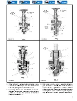
Pressure Indicator is set for 60 psi. When air pressure at
the supply port and under the diaphragm is above 60 psi,
the electrical contacts remain open because the force
exerted by air pressure underneath the diaphragm
overcomes the force exerted by the spring above the
diaphragm.
When air pressure below the diaphragm drops below 60
psi, the spring exerts a force which is greater than the
force exerted by the air pressure below the diaphragm.
This causes the diaphragm (and the piston in the LP-3) to
move and allow the electrical contacts to close. This
completes or closes the electrical circuit to the warning
device, warning the driver of low air pressure in the system.
PREVENTIVE MAINTENANCE
Every six months, 1800 operating hours or 50,000 miles,
check electrical connections. Low Pressure Indicator should
be checked for proper operation by performing Operating
Test as described elsewhere in this sheet.
TESTING FOR SERVICEABILITY
OPERATING TEST
1. If possible, determine the setting of the Low Pressure
Indicator by referring to the label on the valve or the
vehicle manual.
2. Operation of the Low Pressure Indicator may be
checked with ignition switch on by reducing the
system pressure and observing that low pressure
warning occurs when system pressure drops below the
setting of the Low Pressure Indicator. The contacts will
be closed when the warning device operates. If the setting
of the indicator is unknown, the contacts should close
between approximately 70 psi and 50 psi.
LEAKAGE TEST
1. With air pressure present at the supply port, coat the
indicator with soap solution. No leakage permitted.
REMOVING
1. Block the wheels. Otherwise, secure the vehicle with
other than service brakes.
2. The ignition switch should be in the off position.
3. Drain the air from the system.
4. Disconnect the electrical connections at the Low
Pressure Indicator.
5. Disconnect the air line and mounting bolts or unscrew
the Indicator from the fitting and remove.
INSTALLING
1. Install in a convenient location for servicing.
2. Connect to a reservoir pressure line at a high point in
the system for adequate drainage.
3. If installing an LP-2G Indicator, use a supply line of 1/4
O.D. minimum.
4. Connect the Indicator terminals in series with the ignition
switch and the warning device.
DISASSEMBLY
NOTE: It is generally recommended that the Low Pressure
Indicator, if faulty, be replaced with a new unit;
however, service parts are available; and if repairs
are necessary, the following will apply:
LP-2 Unscrew the cover retainer from the body. Remove
cover and remove spring and diaphragm assembly.
LP-3. Remove cover screws, lockwashers. Remove cover,
contact disc, spring, and shim(s). (Note: Shims may or
may not be present.) Remove contact plate, gasket, piston,
and O-Ring diaphragm.
CLEANING AND INSPECTION
Clean all metal parts in mineral spirits.
Inspect all parts for wear, cracks, or deterioration and
replace all parts not considered serviceable with genuine
Bendix parts.
If contact points are not pitted severely, they can be dressed
with a fine file.
ASSEMBLY
LP-2
1. Place and position the diaphragm assembly in the body.
Position the spring so that it rests on the upper
diaphragm follower.
2. Place cover over the diaphragm and screw cover retainer
to the body and tighten securely. (Torque to 110-130
inch pounds.)
LP-3
1. Lubricate bore of body and both sides of the O-Ring
diaphragm with silicone lubricant BW-650-M (Bendix
piece no. 291126).
2. Install O-Ring diaphragm in body. (Note: O-Ring portion
of diaphragm should face supply port.)
3. Install piston in body. Flat side of piston should face
O-Ring diaphragm.
4. Install gasket. (Always use a phenolic gasket in a two
terminal switch and a metallic gasket in the single
terminal.)
5. Position contact plate over fingers of piston. Contact
plate should rest on face of gasket.
6. If shim(s) are used, place shim(s) in cover.
7. Place spring in cover.
8. Place contact point so that it rests on spring.
Содержание LE MIRAGE XLII
Страница 1: ...COACH MANUFACTURER MAINTENANCE MANUAL LE MIRAGE XLII BUS SHELLS PA1553 ...
Страница 2: ......
Страница 12: ...Section 00 GENERAL INFORMATION 10 PA1553 FIGURE 13 METRIC US STANDARD CONVERSION TABLE 00005 ...
Страница 13: ...Section 00 GENERAL INFORMATION PA1553 11 FIGURE 14 CONVERSION CHART 00006 ...
Страница 14: ......
Страница 30: ......
Страница 131: ...section01f tif 1700x2164x2tiff ...
Страница 132: ...section01f tif 1700x2164x2tiff 2 ...
Страница 133: ...section01f tif 1700x2164x2 3 ...
Страница 134: ...section01f tif 1700x2164x2 4 ...
Страница 135: ...section01f tif 1700x2164x2 5 ...
Страница 136: ...section01f tif 1700x2164x2 6 ...
Страница 137: ...section01f tif 1700x2164x2 7 ...
Страница 138: ...section01f tif 1700x2164x2 8 ...
Страница 139: ...section01f tif 1700x2164x2 9 ...
Страница 140: ...section01f tif 1700x2164x2tiff 10 ...
Страница 141: ...section01f tif 1700x2164x2tiff 11 ...
Страница 142: ...section01f tif 1700x2164x2tiff 12 ...
Страница 143: ...The ONLY Motor Coach Power Choice ...
Страница 182: ......
Страница 185: ...Section 04 EXHAUST SYSTEM PA1553 3 FIGURE 2 EXHAUST SYSTEM INSTALLATION W5 04013 ...
Страница 206: ......
Страница 207: ......
Страница 208: ......
Страница 209: ......
Страница 210: ......
Страница 211: ......
Страница 212: ......
Страница 213: ......
Страница 214: ......
Страница 278: ......
Страница 328: ......
Страница 345: ...FAULT CODE MANUAL Created on 00 04 25 15 30 1 FAULT CODE MANUAL B7L B7TL B12 ...
Страница 370: ......
Страница 397: ......
Страница 398: ......
Страница 399: ......
Страница 400: ......
Страница 401: ......
Страница 402: ......
Страница 403: ......
Страница 404: ......
Страница 405: ......
Страница 406: ......
Страница 407: ......
Страница 408: ......
Страница 419: ...SPICER SPECIALITY AXLE DIVISION place product photo here SERVICE MANUAL GENERAL INFORMATION NDS Axle range ...
Страница 425: ......
Страница 438: ...Page No 12 NDS2 issue A Spicer SpecialityAxle Division Technical Publications Spicer Speciality Axle Division ...
Страница 464: ...Page No 18 Manual No NDS8 Spicer Speciality Axle Division Technical Publications Spicer Speciality Axle Division TP1193 ...
Страница 492: ...Section 12 BRAKE AND AIR SYSTEM PA1553 20 FIGURE 38 AIR OPERATED BRAKING SYSTEM W0 WE ...
Страница 493: ...Section 12 BRAKE AND AIR SYSTEM PA1553 21 FIGURE 39 AIR OPERATED BRAKING SYSTEM W5 ...
Страница 500: ...Section 12 BRAKE AND AIR SYSTEM PA1553 28 FIGURE 46 ABS 4S 4M CONFIGURATION ...
Страница 528: ...16 BW2158 Honeywell Commercial Vehicle Systems Company 4 2001 Printed in USA ...
Страница 532: ......
Страница 540: ......
Страница 548: ......
Страница 555: ......
Страница 568: ......
Страница 588: ......
Страница 594: ......
Страница 597: ......
Страница 650: ...52 9 Inch Fraction Decimal and Millimeter Equivalents Chart Up to 1 inch 9 1 9 Conversion Tables ...
Страница 665: ......
Страница 666: ......
Страница 667: ......
Страница 668: ......
Страница 669: ......
Страница 670: ......
Страница 671: ......
Страница 672: ......
Страница 673: ......
Страница 674: ......
Страница 675: ......
Страница 676: ......
Страница 677: ......
Страница 678: ......
Страница 679: ......
Страница 680: ......
Страница 681: ......
Страница 682: ......
Страница 683: ......
Страница 684: ......
Страница 685: ......
Страница 686: ......
Страница 687: ......
Страница 688: ......
Страница 689: ......
Страница 690: ......
Страница 691: ......
Страница 692: ......
Страница 693: ......
Страница 694: ......
Страница 695: ......
Страница 696: ......
Страница 697: ......
Страница 698: ......
Страница 699: ......
Страница 700: ......
Страница 701: ......
Страница 702: ......
Страница 703: ......
Страница 704: ......
Страница 705: ......
Страница 706: ......
Страница 707: ......
Страница 708: ......
Страница 709: ......
Страница 710: ......
Страница 711: ......
Страница 712: ......
Страница 713: ......
Страница 714: ......
Страница 715: ......
Страница 716: ......
Страница 717: ......
Страница 718: ......
Страница 719: ......
Страница 720: ......
Страница 721: ......
Страница 722: ......
Страница 723: ......
Страница 724: ......
Страница 725: ......
Страница 726: ......
Страница 727: ......
Страница 728: ......
Страница 729: ......
Страница 730: ......
Страница 731: ......
Страница 732: ......
Страница 733: ......
Страница 734: ......
Страница 735: ......
Страница 736: ......
Страница 737: ......
Страница 738: ......
Страница 739: ......
Страница 740: ......
Страница 741: ......
Страница 742: ......
Страница 743: ......
Страница 744: ......
Страница 745: ......
Страница 746: ......
Страница 747: ......
Страница 748: ......
Страница 749: ......
Страница 750: ......
Страница 751: ......
Страница 752: ......
Страница 753: ......
Страница 754: ......
Страница 755: ......
Страница 756: ......
Страница 757: ......
Страница 758: ......
Страница 759: ......
Страница 760: ......
Страница 761: ......
Страница 762: ......
Страница 763: ......
Страница 764: ......
Страница 765: ......
Страница 766: ......
Страница 767: ......
Страница 768: ......
Страница 769: ......
Страница 770: ......
Страница 771: ......
Страница 772: ......
Страница 773: ......
Страница 774: ......
Страница 775: ......
Страница 776: ......
Страница 777: ......
Страница 778: ......
Страница 779: ......
Страница 780: ......
Страница 781: ......
Страница 782: ......
Страница 783: ......
Страница 784: ......
Страница 785: ......
Страница 786: ......
Страница 787: ......
Страница 788: ......
Страница 789: ......
Страница 790: ......
Страница 791: ......
Страница 792: ......
Страница 793: ......
Страница 794: ......
Страница 795: ......
Страница 796: ......
Страница 797: ......
Страница 798: ......
Страница 799: ......
Страница 800: ......
Страница 801: ......
Страница 802: ......
Страница 803: ......
Страница 804: ......
Страница 805: ......
Страница 806: ......
Страница 807: ......
Страница 808: ......
Страница 809: ......
Страница 810: ......
Страница 811: ......
Страница 812: ......
Страница 813: ......
Страница 814: ......
Страница 815: ......
Страница 816: ......
Страница 817: ......
Страница 818: ......
Страница 819: ......
Страница 820: ......
Страница 821: ......
Страница 822: ......
Страница 844: ...Section 16 SUSPENSION PA1553 22 FIGURE 26 SWAY BAR FRONT SUSPENSION 16138D FIGURE 27 SWAY BAR REAR SUSPENSION 16014 ...
Страница 964: ......
Страница 978: ......
Страница 980: ......
Страница 982: ......
Страница 988: ......
Страница 994: ......
Страница 998: ......
Страница 1002: ......
Страница 1004: ...PROCEDURE NO PR00044 REVISION 00 Page 2 of 2 Slide out ...
Страница 1008: ......
Страница 1010: ......
Страница 1012: ......
Страница 1018: ......
Страница 1022: ......
Страница 1024: ......
Страница 1032: ......
Страница 1054: ......
Страница 1066: ......
Страница 1070: ......
Страница 1074: ......
Страница 1110: ......
Страница 1116: ......
Страница 1122: ......
Страница 1142: ......
Страница 1162: ...Section 22 HEATING AND AIR CONDITIONING PA1553 16 FIGURE 16 REFRIGERANT CIRCUIT CENTRAL SYSTEM 22247 ...
Страница 1165: ...Section 22 HEATING AND AIR CONDITIONING PA1553 19 FIGURE 17 DOUBLE SWEEP EVACUATION SET UP ...
Страница 1186: ...Section 22 HEATING AND AIR CONDITIONING PA1553 40 FIGURE 42 REFRIGERANT CIRCUIT SMALL SYSTEM 22336 ...
Страница 1191: ...Section 22 HEATING AND AIR CONDITIONING PA1553 45 FIGURE 50 CENTRAL HEATING SYSTEM COMPONENTS 22338 ...
Страница 1201: ...Section 22 HEATING AND AIR CONDITIONING PA1553 55 FIGURE 64 HEATER LINE SHUTOFF VALVES WE W0 ...
Страница 1202: ...Section 22 HEATING AND AIR CONDITIONING PA1553 56 FIGURE 65 SMALL HEATING SYSTEM COMPONENTS 22337 ...
Страница 1208: ......
Страница 1209: ...Compressor 62 11052 Rev A WORKSHOP MANUAL for MODEL 05G TWIN PORT COMPRESSOR R ...
Страница 1210: ...WORKSHOP MANUAL COMPRESSOR MODEL 05G TWIN PORT ...
Страница 1233: ...Compressor 62 11053 Rev B SERVICE PARTS LIST for MODEL 05G TWIN PORT COMPRESSOR 1 2 3 4 5 6 R ...
Страница 1261: ......
Страница 1262: ......
Страница 1263: ...1 ...
Страница 1264: ...2 ...
Страница 1265: ...3 ...
Страница 1266: ...4 ...
Страница 1267: ...5 ...
Страница 1268: ...6 ...
Страница 1269: ...7 ...
Страница 1270: ...8 ...
Страница 1271: ...9 ...
Страница 1272: ......
Страница 1287: ...Section 24 LUBRICATION PA1553 5 FIGURE 2 LUBRICATION AND SERVICING POINTS ON INDEPENDENT FRONT SUSPENSION VEHICLES 24036 ...
Страница 1294: ......
Страница 1305: ...Section 26 XLII SLIDE OUT PA1553 11 ...
Страница 1306: ...Section 26 XLII SLIDE OUT PA1553 12 FIGURE 16 KEYLESS BUSHING INSTALLATION INSTRUCTION ...


