WT-1550-DM Intelligent Direct Modulated Optical Transmitter
- 5 -
3.
Panel Interface and Menu System Description
3.1
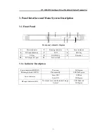
Front Panel
Front panel schematic diagram
1
Power indicator
2
Running indicator
3
Laser indicator
4
RF input indicator
5
LCD
6
ESC key
7
UP key
8
DOWN key
9
Enter key
10
RF output test port
11
Laser switch
3.1.1 Indicator Description
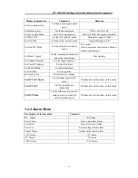
Power indicator (POWER)
Power on
LED green
Running indicator (RUN)
Run normally
LED flash green
Laser indicator
Laser OFF
LED red
Laser ON
LED green
RF input indicator (RF)
No output or exceed the normal range
LED flash red
Normal
LED green
11


