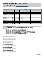
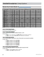
Prestige APS57TM Скачать руководство пользователя страница 6

APS57TM_RevA_07/20

6

 Detailed Descriptions: 

External Components

 RF Antenna / LED / Programming Port

The long-range antenna kit (included) plugs into a 6-pin connector on the Pres�ge module.
1.  Mount the supplied antenna/receiver to a clear spot on the vehicle’s windshield that will not  


block the driver’s vision. A suitable loca�on is high on the windshield near the rear-view mirror. 

2.  Be careful not to mount the antenna/receiver on any metallic window film, as this will affect   


system range.  

3.  Route the antenna/receiver cable to the Pres�ge module, ensuring it does not block or interfere with deployment of 

the airbag (if equipped.) Plug into the antenna port.

 Data Bus Interface (DBI) Port

The 4-pin Data Bus Interface enables a FlashLogic door lock or transponder interface to connect to and communicate 

with the vehicle data bus. The combined system saves installa�on �me as many features that normally require individual 

connec�on can be accessed and controlled through the data bus. Please refer to the D2D (Data to Data) func�on list 

available per vehicle at www.FlashLogic.com.

 Telematics Interface

The 4-pin Telema�cs port enables a connected interface such as CarLink to expand system control to a smartphone or 

tablet. The following features may be able to be ac�vated from a connected device:


• 

Door Lock Control 


• 

Remote Start 


• 

Trunk Release


• 

Auxiliary Output*


• 

Sliding Doors*

Weblink Programming

This port can also be used to connect your FlashLogic Weblink for feature programming and so�ware upda�ng. Once 

connected please visit 

www.flashlogic.com

.

* Must be supported by FLCAN

 FLCART Cartridge Port

This port is for installing the FlashLogic FLCART data immobilizer & door lock interface cartridge used to communicate


with the vehicle’s databus.

 Weblink Programming Port

This 4-pin port is used for programming the FlashLogic FLCART interface cartridge via the FLPROG Weblink or Weblink 

Mobile. Refer to the FlashLogic website for more details.

 FLCART Harness Port

This port is for the harness included with the FLCART interface cartridge. Refer to the FlashLogic website for more details.

Содержание APS57TM

Страница 1: ...for trus ng Pres ge products If you are a consumer please note Professional installation is strongly recommended This manual assumes the installer has adequate knowledge of the following exper se The...

Страница 2: ...ring engine crank Note This wire can be programmed to perform a different func on by changing its op ons Refer to Bank 3 Feature 7 on page 10 4 RED WHITE 12 Volt Input The RED WHITE wire connects to t...

Страница 3: ...e vehicle ground source 1 WHITE Parking Light Relay Output Internal Relay Pin 30 At its default setting the WHITE wire supplies 12 Volt or Ground to the vehicle s park light wire based on the connec o...

Страница 4: ...erent func on by changing its op ons Refer to Bank 3 Feature 19 on page 10 7 BLACK LIGHT GREEN Factory Arm Output At its default setting the BLACK GREEN wire supplies a Ground pulse when the system is...

Страница 5: ...t to the vehicle s Diesel Glow Plug detec on wire Verification This wire will register as 12 Volt while the Diesel Wait to Start Light is illuminated Detailed Descriptions Wire Harness Colors and Func...

Страница 6: ...d and controlled through the data bus Please refer to the D2D Data to Data func on list available per vehicle at www FlashLogic com Telematics Interface The 4 pin Telema cs port enables a connected in...

Страница 7: ...ols will delete the oldest programmed remote control Deleting All Remotes 1 Perform steps 1 3 above 2 Press and hold the valet bu on for ve 5 seconds 3 The system will sound one 1 long beep This indic...

Страница 8: ...Accessory Activated Unlock This Feature is not available on this model Feature 4 Exterior Illumination This Feature is not available on this model 1 Chirp 2 Chirp 3 Chirp 4 Chirp 5 Chirp 6 Chirp 1 Loc...

Страница 9: ...beeps on or off when arming and disarming the system Setting Choices Option 1 Pressing Lock or Unlock at any me will perform the func on with audible beeps Option 2 Pressing Lock or Unlock for 1 5sec...

Страница 10: ...GWR Igni on Accessory 21 Factory Arm Output After Start GWR Igni on Accessory Start 22 Pulse A er Shutdown After Shutdown GWR Igni on Accessory Start 23 Addi onal Unlock Pulse No Pulse IGN ACC GWR IGN...

Страница 11: ...Start Sensing Voltage Level Func on Set the sensitivity of voltage variance measurement to determine if the vehicle has started when Feature 5 is set to option 2 Voltage Setting Choices Option 1 High...

Страница 12: ...e is not available on this model Feature 16 Turbo Timer Setting This Feature is not available on this model Feature 17 Remote Start Activation Func on Set remote start to activate with one two or thre...

Страница 13: ...on Set the functionality of the programmable output Setting Choices Option 1 Pulse During Crank Option 2 GWR Remote Start Status Output Option 3 Igni on Timing Option 4 Accessory Timing Feature 21 Fa...

Страница 14: ...ss 1x Unlock Hold 3 Seconds Panic ON OFF Press 2x Start Programable Hold 3 Seconds Trunk Release Detailed Descriptions System Opera on Remote Control Operation This system includes two 2 remote contro...

Страница 15: ...ocedure 1 Turn the igni on ON 2 Press and release the valet bu on three 3 mes 3 The system will beep 1 one me indica ng you have accessed Bank 1 4 Each cycle of the Igni on OFF ON will advance to the...

Страница 16: ...2 Pulse A er Shutdown After Shutdown GWR Igni on Accessory Start 23 Addi onal Unlock Pulse No Pulse IGN ACC GWR IGN ACC GWR PASD Features Feature Bank 3 Op ons Quick Reference System Programming Bank...

Страница 17: ...the Carlink App The vehicle s parking lights will flash seven 7 mes to indicate the tach signal has been learned If the parking lights do not flash locate another tach source and repeat steps 1 4 abo...

Страница 18: ...rogram the Pres ge system to Lock and Unlock without no ca on beeps 1 Turn the igni on ON then OFF 2 Press and release the valet bu on three 3 mes The system will respond with one 1 beep for ON or two...

Страница 19: ...re ac vated Negative Trigger Door Locks Verification The vehicle wires register Ground when the Lock and Unlock switches are ac vated Lock Unlock Vehicle Door Lock Control Relays RED Lock Output GREEN...

Страница 20: ...itive Multiplex Door Locks Relays required Verification The vehicle wire registers variable 12V values when the Lock and Unlock switches are ac vated Please consult the vehicle speci c wire and loca o...

Страница 21: ...d Aftermarket Actuators Relays and door lock actuators required Lock Unlock 87 87a 86 85 30 87 87a 86 85 30 Fused 12 Volt Battery Souce Fused 12 Volt Battery Souce RED Lock Output Green Unlock Output...

Страница 22: ...V 3 Blue Data TX 2 Black Ground 1 White Data RX CarLink This Harness is included with the FLCART For Wire Informa on and Diagram Please Refer to Vehicle Speci c FlashLogic Install Guide Visit www Flas...

Отзывы: