background image

Содержание C354

Страница 1: ...d to repair and maintain this product This document contains general product information software diagnostic procedures when available preventative maintenance procedures inspection and adjustment pro...

Страница 2: ...be necessary to either equip the unit with the optional external power supply or have an assistant pedal on the unit while voltage measurements are being taken Because of the danger of working on the...

Страница 3: ...e Read the owner s manual and follow all operating instructions Operate the EFX on a solid level surface Visually check the EFX before beginning service or maintenance operations If it is not complete...

Страница 4: ...e Precor dealer website at www precor comlconnection Tools Required Multimeter Anti static kit 4 6 gear puller Precor part number 20030 108 belt gauge US and metric end wrench set US and metric socket...

Страница 5: ...rarms stairarm ramps and stairarm wheels using water or a 30 1 solution of Simple Green and water Wipe the surface of the electronic console with a damp sponge or soft cloth Dry with a clean towel A 3...

Страница 6: ...form the software diagnostics Check LED and keypad function Record the odometer reading Check speed sensor function is the stride rate displayed when the unit is in operation If not see Procedure 6 3...

Страница 7: ...presses The allowable delay between key presses is short If too much time is taken between key presses the access procedure will be aborted If the access is aborted it will be necessary to start over...

Страница 8: ...e key is functioning Check each key in this manner including the numeric keyboard Press and hold the ENTER key for 2 seconds to advance to the heart rate test 1 2 3 4 e 5 6 The message HEART RATE TEST...

Страница 9: ...the ENTER key to advance to software version 7 The message SOFTWARE VERSION will be displayed followed by the software versions of the upper and lower PCA s For example UPPER 1 01 LOWER 1 01 Press th...

Страница 10: ...rement Use the and keys to select either U S Standard or METRIC measurements Press the ENTER key to advance to maximum workout time 6 The message SET MAX WORKOUT TIME will be displayed followed by the...

Страница 11: ...to Precor When a problem occurs record the following information Model and serial number Software version number Note Look at the PROM mounted on the upper PCA A label on the PROM indicates the softw...

Страница 12: ...bbing hitting grinding or squeaking noises 5 If the EFX makes unusual noises or the electronic display does not change appropriately troubleshoot per Section 6 6 Press the RESISTANCE A key until you r...

Страница 13: ...at will conveniently read up to 50 Q 3 Remove the three generator output leads from the lower PCA brown from terminal M3 blue from terminal M4 and violet from terminal M5 4 With an ohmmeter read betwe...

Страница 14: ...3 Remove the six phase generator connector from the lower PCA refer to Diagram 5 2 below 4 With an ohmmeter read between terminals 1 2 terminals 1 3 terminals 1 5 terminals 1 6 and terminals 1 7 on th...

Страница 15: ...Fitness Crosstrainerl 6 Replace the generator per Procedure 7 17 Reconnect the intermediate cable removed in step 5 to the replacement generator and the lower PCA 7 Reconnect the red battery lead to t...

Страница 16: ...mounting bracket may be extremely hot 2 Remove the three screws that fasten the load resistor assembly and shield to the frame upright Rotate the load resistor assembly 180 degrees and set it on the t...

Страница 17: ...been changed continue with step 7 Place a 20030 108 or equivalent belt gauge on the generator belt as shown in Diagram 5 4 Diagram 5 4 Generator Belt Tension Measurement Adjustment Nut Jam Nut 7 The b...

Страница 18: ...belt tension should be set 20 Ibs higher than the previous readings Therefore a new input pulley belt should be tensioned to 120 Ibs and a new generator belt should be tensioned to 80 Ibs Over time an...

Страница 19: ...30 31 or 32 continue with step 3 otherwise see Procedure 6 3 C534 or Procedure 6 4 C534i 2 Pry the end cap out of the front of the frame base tube See Diagram 6 1 3 Carefully withdraw both cables and...

Страница 20: ...tor and continue with step 7 7 Remove the upper display housing per Procedure 7 1 steps 1 to 4 Disconnect the upper interconnect cable from the mid point connector Substitute a known good interconnect...

Страница 21: ...ct the ground lead of the wrist strap to the units frame If the EFX powers up and functions normally until a particular key s is pressed skip to step 12 If a Error 5 key depressed message is immediate...

Страница 22: ...ss the diagnostics program per procedure 3 2 If the key s necessary to access the diagnostic program is not functioning skip to step 14 12 Test the keypad per Procedure 3 2 step 4 13 If all of the key...

Страница 23: ...ected by an electrician 5 Troubleshoot the generator per Procedure 6 5 C534 or Procedure 6 6 C534i 6 If the generator was found to be good the problem will be in either the lower PCA upper PCA or the...

Страница 24: ...nnector 10 Troubleshoot the upper to lower PCA interconnect cables per Procedure 6 1 11 If the upper to lower interconnect cables are found to be good replace the upper PCA 12 If you have performed al...

Страница 25: ...ted by an electrician 5 Troubleshoot the generator per Procedure 6 5 C524 or procedure 6 6 C524i 6 If the generator was found to be good the problem will be in either the lower PCA upper PCA or the up...

Страница 26: ...13 DS1 LED J2 Connector 10 Troubleshoot the upper to lower PCA interconnect cables per Procedure 6 1 11 If the upper to lower interconnect cables are found to be good replace the upper PCA 12 If you h...

Страница 27: ...e being taken Because of the danger of working on the unit while it is in motion using the optional external power supply is strongly recommended 1 Perform the generator resistance test per Procedure...

Страница 28: ...re being taken Because of the danger of working on the unit while it is in motion using the optional external power supply is strongly recommended 1 Perform the generator resistance test per Procedure...

Страница 29: ...arning and Caution statements listed in Section One Things You Should Know 2 Attach the anti static wrist strap to your arm then connect the ground lead of the wrist strap to the units frame 3 Remove...

Страница 30: ...and tighten the upper PCA mounting screws 8 Reconnect the keyboard cable to the upper PCA 9 Reconnect the upper interconnect cable to the upper PCA 10 Remove the ground lead of the wrist strap from th...

Страница 31: ...uing with this procedure review the Warning and Caution statements listed in Section One Things You Should Know 2 Remove the rear cover per Procedure 7 20 3 Attach the wrist strap to your arm then con...

Страница 32: ...e 3 conductor cable from the generator as follows brown to AC1 blue to AC2 and violet to AC3 Connect the green yellow frame ground wire to M8 From the battery connect the red wire to M6 and the black...

Страница 33: ...uing with this procedure review the Waming and Caution statements listed in Section One Things You Should Know 2 Remove the rear cover per Procedure 7 20 3 Attach the wrist strap to your arm then conn...

Страница 34: ...e input power jack to the J4 connector The 6 conductor cable from the generator as to connector J1 From the battery connect the red wire to M6 and the black wire to M7 of the lower PCA Connect the two...

Страница 35: ...a thin bladed screwdriver See Diagram 7 4 3 Carefully withdraw both cables and mid point connector Diagram 7 4 Interconnect Cables and Mid Point Connector Lower Interconnect Cable Upper Interconnect...

Страница 36: ...nnect cable from the upper PCA See Diagram 7 4 Remove the four screws that fasten the display housing backplate to the main column Remove the display housing backplate 10 Securely tape one end of the...

Страница 37: ...of the rear cover 2 Remove the stairarm assembly as described in Procedure 7 12 steps 2 to 4 Note Notice the position of the two crank arms When the crankarms are replaced they must be positioned so t...

Страница 38: ...nput pulley shaft Torque the nut to 300 in lbs 7 Replace the stairarm assembly as described in Procedure 7 12 steps 11 to 12 8 If you are replacing both crankarm assemblies repeat steps 6 and 7 for th...

Страница 39: ...wer PCA Remove the input pulley belt Set the replacement input pulley belt in it s mounting position on the step up pulley assembly Set the step up pulley assembly with the generator and input belt at...

Страница 40: ...erator and remove its drive belt 9 Slide the step up pulley assembly with both the generator and input belts out of the drive unit 10 Remove and discard the generator belt Set the replacement generato...

Страница 41: ...Crosstrainerl 17 Tension both belts per Procedure 5 3 Note the differences between tensioning a new belt and a existing used belt 18 Replace the red battery lead removed in step 1 and check unit oper...

Страница 42: ...he stairarm assemblies as described in Procedure 7 12 steps 2 to 4 3 Remove the crankarm assemblies as described in Procedure 7 5 steps 2 to 5 4 Remove the input pulley assembly mounting nuts 2 per pi...

Страница 43: ...block bearing until the edge of the pillow block bearing is parallel with the edge of the frame upright Replace the nuts in the other pillow block bearing and torque to 500 in pounds 10 Replace the cr...

Страница 44: ...s described below a Straighten the locking tabs and turn the left and right tension bolts counterclockwise until tension is removed from both belts See Diagram 5 3 b Remove both tension bolts and slid...

Страница 45: ...he second wheel axle screw the axle rotates and the screw does not unthread insert a 5 32 allen wrench into the end of the axle from which the screw has been removed The allen wrench will hold the axl...

Страница 46: ...bolts that fasten the stairarm pedal onto the stairarm 2 Remove the stairarm pedal from the stairarm 3 Set the replacement stairarm pedal at it s mounting position on the stairarm 4 Install and hand...

Страница 47: ...s are removed 1 Procedure 1 Set the on off switch in the off position then unplug the power cord from the wall outlet 2 Loosen and remove the two bolts that fasten the stairarm pedal onto the stairarm...

Страница 48: ...bolts to 60 in lbs 10 Remove and replace the wheel per procedure 7 10 11 Slide the replacement stairarm assembly onto the stairarm pivot block Install and hand tighten the stairarm pivot block mountin...

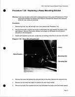
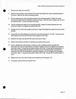
Страница 49: ...e unit 3 Remove the screws that fasten the ramp end cap to the ramp assembly Slide the ramp end cap out of the ramp assembly and rotate the ramp assembly toward the rear of the unit 4 Remove four rear...

Страница 50: ...3 8 Set the ramp assembly at it s mounting position Hand start the rear mounting bolts and the two front bottom mounting bolts Torque the rear mounting bolts to 120 inch pounds Torque the two front bo...

Страница 51: ...dlebar t Lower Bolt ir o 1 Mounting Bolt 2 Remove the three bolts that fastens the handlebar to the upper pivot arm and remove the handlebar 3 Set the replacement handlebar at its mounting position an...

Страница 52: ...Diagram 7 12 2 Remove the retaining ring that fastens the lower pivot arm to the stairarm connector Diagram 7 12 Pivot Arm Connector 3 Remove the stairarm connector Remove the wave washer from the piv...

Страница 53: ...ning ring that fastens the lower pivot arm to the stairarm connector See Diagram 7 13 2 Remove the bolt that fastens the lower pivot arm to the handlebar arm Diagram 7 13 Pivot Arms Stairarm Connector...

Страница 54: ...washer and spacer from the front inside and rear of the handlebar to stairarm link Remove and discard the handlebar to stairarm link 4 Slide one of the spacers removed in step 3 into the front of the...

Страница 55: ...ered Elliptical Fitness Crosstrainerl 6 Torque the both the front and rear handlebar to stairarm link mounting bolts to 156 inch pounds 7 Set the on off switch in the on position and test the EFX per...

Страница 56: ...r pivot arm The bearing shaft will be very tight a long handled socket wrench with a 7 16 hex key will be necessary for removal See Diagram 7 15 Diagram 7 15 Upper Pivot Arm 1 Bearing Shaft 3 Remove t...

Страница 57: ...ector J5 from the upper PCA Remove the display housing front panel Remove the four screws that fasten the display backplate to the upper main column Remove the display housing backplate Pry the end ca...

Страница 58: ...and torque them to 240 in llbs Rotate the right hand handlebar with upper pivot into it s mounting position Thread the upper pivot into the main column and torque it to 100 ft llbs Replace the left a...

Страница 59: ...eplaced 4 If you are removing the top cover See Diagram 7 18 remove the two phillip screws that fasten the top cover section to the frame upright Remove three screws that fasten the top cover section...

Страница 60: ...Replace and tighten the two phlliips screws that fasten the front cover section to the frame 8 Set the top cover section in it s mounting position replace and tighten the two phillips screws that fas...

Страница 61: ...the load resistor wiring from both terminals of the resistors 4 Remove the screw that fastens one of the load resistor clips to the mounting bracket Remove the resistor s being replaced 5 Slide the re...

Страница 62: ...p 2 8 Route the load resistor wires into the slots at the top of the frame upright This will keep the wires away from all moving parts such as the stairarms 9 Reconnect the red battery lead removed in...

Страница 63: ...enerator Mounting Adjustment Bolt Mounting Bolt 5 Remove the four mounting bolts that fasten the generator to the frame remove the generator belt from the generator Remove the generator adjustment bol...

Страница 64: ...tension is correct torque the four generator mounting bolts to 150 inch pounds Securely tighten the forward nut on the adjustment bolt 9 Reconnect the red battery lead removed in step 1 and replace th...

Страница 65: ...locking nut on the generator s adjustment bolt and thread the adjustment bolt into tab to remove tension from the generator s drive belt Remove the drive belt from the generators pulley 6 Remove the...

Страница 66: ...ting position replace and tighten the two bearing clamp mounting screws removed in step 9 11 Hand start but do not tighten the four mounting nuts removed in step 6 The generator must be able to move i...

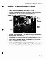
Страница 67: ...nnect the J3 and J4 connectors from the lower PCA 4 While supporting the lower PCA and battery assembly remove the four screws that fasten the battery bracket to the frame upright 5 Swing the lower PC...

Страница 68: ...he open end of the battery bracket 8 Fasten the lower PCA and battery assembly to the frame upright with the screws removed in step 4 9 Reconnect the J3 and J4 connectors to the lower PCA 10 Reconnect...

Страница 69: ...tor cable J2 data cable J3 lift cable J4 power adapter M1 and M2 load cables from the lower PCA Use an antistatic wrist connect to a grounding point when performing steps 5 6 11 and 12 Remove the four...

Страница 70: ...the bracket 9 Replace the front retaining bracket and fasten it with its mounting nut 10 Remove the electrical tape from the battery terminals and reconnect the battery wires as follows the red wire...

Страница 71: ...e rear cover support See Diagram 7 26 Input Jack Mounting Screw Mounting Nut Input Jack Mounting Plate Remove the nut that fastens the power input jack to the power input jack mounting plate Remove th...

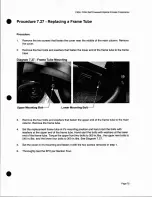
Страница 72: ...four bolts and washers that fasten the upper end of the frame tube to the main column Remove the frame tube 4 Set the replacement frame tube at it s mounting position and hand start the bolts with wa...

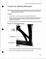
Страница 73: ...per Procedure 7 20 2 Remove three bolts washers and single nut that fasten the right stairarm connector to the right stairarm Remove three bolts washers and single nut that fasten the left stairarm co...

Страница 74: ...ween the ramp and rear ramp bracket to 12 ft llbs Torque the two bolts between the ramp and the front ramp support to 20 ft Ibs Replace the ramp end cap with the screw removed in step 3 Rotate both st...

Страница 75: ...ashers and single nut that fasten the right stairarm connector to the right stairarm Remove three bolts washers and single nut that fasten the left stairarm connector to the left stairarm 3 Rotate bot...

Страница 76: ...een the ramp and rear ramp bracket to 12 ft llbs Torque the two bolts between the ramp and the front ramp support to 20 ft Jlbs Replace the ramp end cap with the screw removed in step 4 Rotate both st...

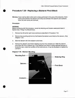
Страница 77: ...You Should Know 1 Remove the left and or right cover sections as described in Procedure 7 20 2 Remove the mounting bolt and nut that fastens the stairarm pivot block to the stairarm See Diagram 7 30...

Страница 78: ...pin and replace the retaining ring removed in step 4 6 Slide the stairarm onto the stairarm pivot block Install and hand tighten the stairarm pivot block mounting hardware Torque the stairarm pivot b...

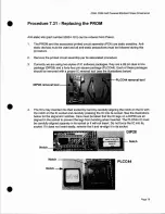
Страница 79: ...are package PLCC44 Each of these packages should be removed with a proper IC removal tool see the illustrations below PLCC44 removal tool DIP28 removal tool 4 The IC s may inserted into their socket b...

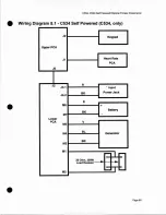
Страница 80: ...ss Crosstrainer Wiring Diagram 8 1 C534 Self Powered C534 only J2 Keypad Upper PCA J1 Heart Rate PCA J5 J2 R J4 1 Input BK Power Jack J4 2 R M6 BK Battery M7 Lower PCA V M5 M4 BL Generator BR M3 M1 I...

Страница 81: ...t J CD rator C534 Self Powered EFX UPCA Keypad J2 Microprocessor System on Heart Rate Jl peA I I Mid Point Connector LPCA It 5 1 l 1 00 J2 2 5 e J2 7 2 e n 3 R Me at 8 5VDC f I M2 P W l rBK lol7 Suppl...

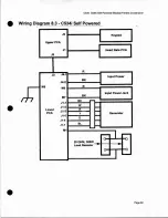
Страница 82: ...ri 1g Di_agram 8 3 C534i Self Powered J2 Keypad UpperPCA J1 Heart Rate PCA J5 R J2 J4 1 Input Power BK J4 2 M8 M6 R BK Input Power Jack M7 I I BK J1 1 J1 2 W Lower J1 3 R 100 PCA y Generator J1 5 G J1...

Страница 83: ...Keypad I 1 u j IWJ oSor 5ys m f 14 If 1 L 1 Heart Ra1e l peA l r nI C d r J 1 11 1 1 u l LPCA tI l 0 U DK R R RK Jl le I Jl 1 uu p R 5 tl t f Il C il f I I d c3 r II S OC I U It D Power 3 oil S JPp y...

Отзывы: