background image

1

PM-1440E-LB 11-13-17 V1

Copyright © October 2017 Quality Machine Tools, LLC

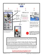
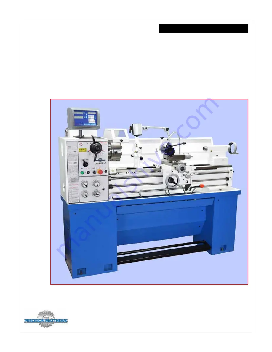
Model PM-1440E-LB Lathe


High precision 3 HP gap-bed machine

2 inch spindle bore

D1-5 camlock spindle mount

40 in. between centers, 14 in. swing over bed, 19-3/4 in. over gap 

8 spindle speeds from 70 to 2000 rpm

Full range of Inch and Metric thread cutting

Bidirectional power feed for saddle & cross-slide

Weight, including cast iron stand & coolant system 1800 lb

PM-1440E-LB

 Shown here with 2-axis DRO (option), 3-jaw chuck, coolant sys-

tem, footbrake, worklight, steadies, wedge-type QC toolpost, cast iron stand

Содержание PM-1440E-LB

Страница 1: ...n between centers 14 in swing over bed 19 3 4 in over gap 8 spindle speeds from 70 to 2000 rpm Full range of Inch and Metric thread cutting Bidirectional power feed for saddle cross slide Weight inclu...

Страница 2: ...e and the information given here with little or no impact on functionality If you have questions about any aspect of the manual or your machine please email us at service precisionmat thews com Your f...

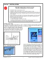
Страница 3: ...ms rated for a total weight of at least 1 1 2 tons If using slings as Figure 1 1 use spreaders to keep them clear of the leadscrew etc Move the saddle and tailstock for best balance To fork lift the m...

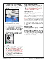
Страница 4: ...en FAQs page 2 or 3 The chuck cover is up In other words no warping Make sure all leveling mounts and or shims are properly weight bearing firmly in contact with the floor Check and ad just level from...

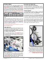
Страница 5: ...erlock stops the motor when the belt cover is removed Figure 1 8 Motor control lever Mid travel OFF DOWN Forward UP Reverse TEST RUN PROCEDURE Run the spindle for a few minutes forward and reverse at...

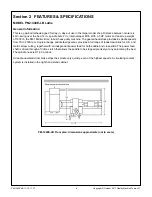
Страница 6: ...geared headstock provides 8 spindle speeds from 70 to 2000 rpm A quick change saddle feed gearbox provides a full range of leadscrew ratios for U S and metric screw cutting together with an independen...

Страница 7: ...l 3 3 4 in Drive system VFD drive with 2 speed gearbox Low range rpm 70 to 300 High range rpm 460 to 2000 Saddle drive thread cutting Leadscrew 8 tpi Inch threads Choice of 34 from 4 to 56 TPI Metric...

Страница 8: ...les can be hazardous Be sure the work area is properly lit Never leave chuck keys wrenches or other loose tools on the machine Be sure the workpiece toolholder s and machine ways are secure before com...

Страница 9: ...at the following interlocks function correctly E Stop button Chuck guard Belt cover to the left of the headstock Footbrake Before doing ANYTHING check the installa tion instructions and power up proce...

Страница 10: ...ED For normal turning and facing operations To activate the feed shaft 1 Set the Direction lever Figure 3 1 4 to the left and 2 Set the upper right knob on the gear box to N Figure 3 1 9 Selections 1...

Страница 11: ...leadscrew in this case 8TPI to cut metric threads For U S TPI thread cut ting there is no transposing requirement the 127T gear acts only as an idler transferring drive directly from the head stock to...

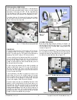
Страница 12: ...It is mostly preferable to feed the tool into the workpiece at an angle so it cuts mostly on the left flank of the thread Figure 3 10 The correct angle relative to the cross slide zero degrees is deba...

Страница 13: ...orkpiece the split nut lever is lowered to engage the leadscrew This can be done at any point provided the split nut remains engaged throughout the entire multi pass thread cutting process When the fi...

Страница 14: ...too tight thread and one that runs perfectly Assuming that the compound is set over at between 29 and 30 degrees the total depth of cut is approximately 0 69 times the thread pitch P this equates to...

Страница 15: ...to the normal axis for rou tine operations One way to avoid cut and try is to prepare in advance a bar of say 1 diameter quality ground stock with precise center drillings at both ends do this by indi...

Страница 16: ...To set the fingers on the workpiece first swing open the upper casting Make certain that all three fingers are freely adjustable by thumbwheel If not loosen and re lock the set screws ar rowed Raise...

Страница 17: ...pieces even custom made cradles to assist straight line installation and removal Before installing make certain that the mating surfaces of the chuck faceplate and spindle are free of grit and chips T...

Страница 18: ...move the four large socket head screws se curing the insert to the bed To minimize cosmetic damage cut through the paint and filler along the joint between insert and bed using a sharp knife or pointe...

Страница 19: ...r in mind that the ratio of product to water is important too much water causes excessive corrosion and other problems Check the mix from time to time using a refractometer If this is not available ma...

Страница 20: ...uch as Mobil Vactra No 2 or equivalent Machine ways dovetails ISO 68 way oil such as Mobil Vac tra No 2 or equivalent External change gears light general purpose grease NLGI No 2 or equivalent Leadscr...

Страница 21: ...empty completely 5 Replace the drain plug To refill the gearbox use a funnel attached to a flexible plastic tube inserted into the fill hole 6 Add oil to the halfway mark on the sight glass about 2 q...

Страница 22: ...like those on the cross slide and compound It provides no front to back force serving only to hold the back of the saddle down onto the bed fore aft control is the function of the bed s triangular ten...

Страница 23: ...l locking set screw bottomed in the well prevents loos ening of the flange screw To correct backlash due to loose coupling between leadscrew and thrust bearings back out the set screw a turn or two th...

Страница 24: ...tailstock to the right just far enough to allow access to the hex nut below the tailstock bed plate Tighten the nut as necessary Figure 4 15 Footbrake microswitch LH stand cabinet Figure 4 16 Brake a...

Страница 25: ...the drill rod snugly between centers as Figure C Lock the tailstock 6 Set a dial indicator on the cross slide to eliminate vertical error use a flat disc contact not the usual spherical type if a disc...

Страница 26: ...ches protruding Figure E Center drilling is not need ed 1 Adjust the chuck for minimum runout at position 1 2 Check the runout at 2 Pointer movement when traversing is not a concern at this stage 3 If...

Страница 27: ...direction Figure A1 Misaligned headstock In this illustration the workpiece diameter increases as the cut ting tool moves toward the chuck Correct this by screwing in A a fraction of a turn to rotate...

Страница 28: ...osed for the control circuit to be energized E Stop Chuck Guard Belt Cover Foot Brake Additionally the 24V Master switch must be ON and the Motor Control Forward Reverse switches SQ1 SQ2 must be in th...

Страница 29: ...29 Copyright October 2017 Quality Machine Tools LLC PM 1440E LB 11 13 17 V1 PM 1440E LB Electrical box...

Страница 30: ...30 PM 1440E LB 11 13 17 V1 Copyright October 2017 Quality Machine Tools LLC Motor control switches Motor control cam...

Страница 31: ...31 Copyright October 2017 Quality Machine Tools LLC PM 1440E LB 11 13 17 V1 Stand components There may be detail differences between this representative drawing and the ma chine as supplied...

Страница 32: ...12 3 GB1096 79 Key 4 GB97 1 86 Washer 8 Lathe bed components 5 GB5783 86 Bolt M8 25 6 90S 4 Motor 7 33 6032 Clamp knob 8 32 01107 Pulley The following schedule refers to the drawings on this page and...

Страница 33: ...6 33 6050 Motor control lever 47 GB4141 11 84 Knob 48 GB70 85 Screw M6 16 49 33 6045 Bracket 50 GB2089 80 Compression spring 1 6 20 51 33 6047 Washer 52 GB818 85 Screw M5 6 53 32 12206A Cover plate 54...

Страница 34: ...0E LB 11 13 17 V1 Copyright October 2017 Quality Machine Tools LLC Headstock 1 FEED DIRECTION SPEED RPM H L RANGE There may be detail differences between this representative drawing and the machine as...

Страница 35: ...1 21 32C 04115 Flange 22 GB70 85 Screw M6 35 23 GB78 85 Set screw M6 16 25 32 04402 Shift tongue 26 32C 04255 Shaft 27 32 04235 Collar 28 GB308 84 Steel ball 6 29 GB2089 80 Spring 1 6 7 30 32C 04242...

Страница 36: ...ht October 2017 Quality Machine Tools LLC Headstock 2 There may be detail differences between this repre sentative drawing and the machine as supplied A Spindle B Internal shaft C Power input D Intern...

Страница 37: ...211 Rocker stud 64 32 04217 Gear collar 65 GB894 1 86 Circlip 35 66 32 04252 C Shaft 67 GB1096 79 Key 5 50 68 32 04218 Gear 29T 2 69 32 04219 Gear 46T 2 70 32 04220 Gear 38T 2 71 GB78 85 Screw M8 16 7...

Страница 38: ...l differences between this repre sentative drawing and the machine as supplied Not shown spider assembly LH end of spindle 105 A Spindle B Internal shaft C Power input D Internal shaft E Output to cha...

Страница 39: ...9 Key 8 85 108 32 04231 Cam Camlock 109 32 04505 Gasket 110 GB276 88 Ball bearing 111 GB70 86 Screw M6 18 112 32 04229 Spring 113 32 04230 Camlock stud 114 GB1235 76 O Ring 25 2 4 115 32 04238 D Shaft...

Страница 40: ...6X18 10 33 6027 Bearing housing 11 33 6025 Sleeve 12 32C 051 12 Swing Frame 13 32 05228 Setting Bolt Items 6 7 are not separate they are cut from a single blank 14 GB70 85 Socket head screw M6x15 15...

Страница 41: ...ass A12 6 32C 2030 2 Panel 7 RUN6246 101099 Pointer 8 GB80 85 Set screw M6x8 9 GB77 85 Set screw M8x12 10 GB879 86 Spring pin 5x40 11 6220 2050 Knob 12 GB2089 80 Spring 1x5x20 13 GB308 89 Steel ball 6...

Страница 42: ...42 PM 1440E LB 11 13 17 V1 Copyright October 2017 Quality Machine Tools LLC Gearbox There may be detail differences between this representative drawing and the machine as supplied...

Страница 43: ...ng 6202 2RS 6 33 2004 Spacer 7 GB894 2 86 Retaining ring 20 8 GB894 2 86 Retaining ring 28 9 33 2006 Gear 10 33 2007 Gear 11 GB1 096 79 Key 4x22 12 33 2008 Gear 13 Q ZB285 3 Oil fill plug ZG 3 8 14 GB...

Страница 44: ...Quality Machine Tools LLC Saddle cross slide compound There may be detail differences between this repre sentative drawing and the machine as supplied There may be detail differences between this rep...

Страница 45: ...ew 26 Support flange 27 Screw 28 Cover plate 29 Screw M8 30 Screw M8 31 LH gib plate 32 RH gib plate 33 Wiper 34 Backing plate 35 Screw 36 Nut 37 Screw M8 38 Gib support 39 Gib 40 Backing plate 41 Wip...

Страница 46: ...46 PM 1440E LB 11 13 17 V1 Copyright October 2017 Quality Machine Tools LLC Apron There may be detail differences between this representative drawing and the machine as supplied...

Страница 47: ...8 33 4045A Helical gear 32T 39 GB95 85 Washer 40 GB41 86 Nut M8 48 Q ZG285 3 Drain plug 1 8 49 33 4050 Split nut indicator 50 GB1160 89 Sight glass 51 GB879 86 Roll pin 5 35 52 GB2089 80 Spring Apron...

Страница 48: ...40E LB 11 13 17 V1 Copyright October 2017 Quality Machine Tools LLC Tailstock Tailstock locking lever not shown There may be detail differences between this representative drawing and the machine as s...

Страница 49: ...2 08207 Quill lock lever 13 32 08208 Quill lock rod 14 32 08209 Screw 15 GB78 85 Screw M10 45 16 32 08204 Washer 17 32 08501 Handle 18 32 07207b2 2 Shoulder screw 19 32 07207b1 2 Screw 20 GB73 85 Scre...

Страница 50: ...Upper casting 9 GB6170 86 Nut M6 10 GB79 85 Screw M6 18 11 GB65 85 Screw M6 30 12 32 10206 Clamp screw 13 GB879 86 Dowel pin 5 24 14 32 10102 Lower casting 15 GB6170 86 Nut M12 16 GB97 1 86 Washer 17...

Отзывы: