


BI-DIRECTIONAL TOOL TURRET
27
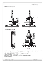
2. Partial Assembly of spindle
1. Assemble Main Spindle (54) Main / Indexing flange (31) and Fixed coupling (50) with respect to the reference marks
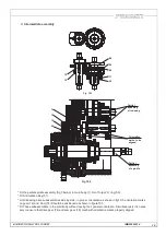
2. Place Drum cam sub assembly (fig 10.0) on the spindle, Take care to align the orientation marks on Fixed
coupling (50) and Sliding coupling (39).
3. Also align Orientation marks on Cam gear (18) and sliding coupling (39)
4. Place components 17, 16, 15 in position
5. Use indexing gear with pinion tighten nut 14 till it buts against the shaft shoulder.
6. Spindle sub assembly.
Fig 9.4a
Fig 9.4b
Fig 9.4d
14
13
64
15
16
17
Drum cam
subassembly
54
32
33
34
50
Plate
IMB50052014
Fig 9.4c
45
97
44
46
48
47
98
96
30
29
42
2.1. Coolant Flange Assembly
Содержание BTP-50
Страница 1: ...INSTRUCTION MANUAL B T P 50 BI DIRECTIONAL TOOL TURRET IMB50052014 ...
Страница 2: ......
Страница 4: ......
Страница 31: ......


