


5/16
CONTROL CONNECTION
Connection between the controller and a projector and between one projector and another must be made with a 2
core-screened cable, with each core having at least a 0.5mm diameter. Please use the projector’s cannon 5- pin signal
input and output cables as connection. The 5-pin signal connections are connected as shown in the figure above.
Note: Care should be taken to ensure that none of the pins touch the metallic body of the plug or each other. The body of
the plug is not connected in any way. The projector accepts digital control signals in protocol DMX512 (1990).
Connect the controller’s output to the first fixture’s input, and connect the first fixture’s output to the second fixture’s input
and connect the rest fixtures in the same way. Eventually connect the last fixture’s output to a DMX terminator as shown
in the figure below.
Each unit should be connected to power supply individually and the voltage and frequency of the power supply should
match those indicated on nameplate.
DMX TERMINATOR
In the Controller mode, at the last fixture in the chain, the DMX output has to be connected with a DMX terminator. This
prevents electrical noise from disturbing and corrupting the DMX control signals.
The DMX terminator is simply an XLR connector with a 120
Ω
(ohm) resistor connected across pins 2 and 3, which is
then plugged into the output socket on the last projector in the chain. The connections are illustrated below.
Содержание LED Studio 3300D
Страница 11: ...11 16 SIZES ...
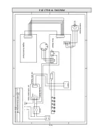
Страница 12: ...12 16 ELECTRICAL DIAGRAM ...
Страница 13: ...13 16 ...
Страница 15: ...15 16 ...


