S3x-HB-1-11
33
4
Graphical User interface
The 7” touch panel displays the current system topology and provides the means to control many
parameters of the system and attached devices. A USB mouse and keyboard may also be used as input
devices.
4.1 Overview Screen
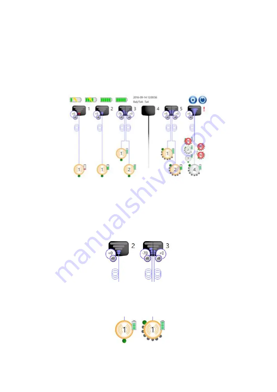
The overview screen (shown in Figure 32) shows a top level,
“at a glance view” of the system
configuration, including some key performance parameters.
Figure 32: Top-level GUI display menu
The Rx module icons (shown in detail in Figure 33) show the link gain and the received light level (RLL)
from the active Tx head/input combination. The received light level from the active Tx head is shown as a
bar chart in the centre of the Rx module icon. A bubble on the side of the icon displays the current gain
for the active input link (this is configurable from the transmitter screen
– see section 4.3). Rx1 and Rx6
modules will show a single bar chart and a single gain, where an Rx2 module will show one for each fibre
optic channel (as an Rx2 can have two simultaneously active optical links). The active Tx head (for an
Rx6 module) is configurable from the relevant Rx module screen. Any alarms (such as a low received
light level) will cause the position number to toggle to a red exclamation mark (as seen in Figure 32).
Pressing on an Rx module icon will display the Rx module configuration screen (section 4.2).
Figure 33: Rx Module icons (left: Rx1, right: Rx2)
The Tx head icons (shown in detail in Figure 34), show the active input (denoted by the green circle) and
the battery level. Any alarms (such as a low battery) will cause the icon to highlight in red (as seen in
Figure 32). The active input (for at Tx8 head) is configurable from the relevant Tx head screen. Pressing
on a Tx head icon will display the Tx head configuration screen (section 4.3).
Figure 34: Tx head Icons (left: Tx1, right: Tx8)
Содержание Sentinel 3
Страница 59: ...S3x HB 1 11 59 8 2 Tx8 battery ...


