


23
Zenex Plus
User Manual
DIGITAL INPUTS
Door Open
Timer Start
Alarm Acknowledge
Potential-free contact closure input terminals are provided as digital
inputs. An ‘Open’ or ‘Close’ switch position is detected as input. Refer
Figure 6.5.
DIGITAL OUTPUTS
Heater Control Output
Compressor Control Output
Process Alarm Output
Event Alarm Output
All the above Control & Alarm outputs are Voltage pulses (12VDC @ 40mA) for driving external SSR or Relay. The ‘+’ and ‘-’
terminals are for voltage ‘Source’ and ‘Return’ paths, respectively. Refer Figure 6.4 below.
Figure 6.4
Heater
Control
15
16
17
+
-
14
2
3
4
1
Old Version
New Version
19
20
21
18
6
7
8
5
+
-
+
-
+
-
Compressor
Control
Process
Alarm
Event
Alarm
Figure 6.5
23
24
25
22
14
15
16
13
Old Version
New Version
DI-2
DI-3
DI-1:Door Open
DI-2:Timer Start
DI-3:Alarm ACK
DI-1
Figure 6.6
PC
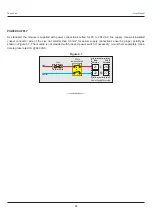
COMMUNICATION PORT
The controller Communication Port is RS485 and requires a similar port at the host (master) end. If, however, the host port is
different (say, RS232 or USB), use appropriate protocol converter (say, RS485-RS232 or USB to RS485) for interface.
For reliable noise free communication, use a pair of twisted wires inside screened cable as shown in Figure
. The wire
6.6
should have less than 100 ohms / km nominal DC resistance (Typically 24 AWG or thicker). Connect the terminating resistor
(Typically 100 to 150 ohm) at one end to improve noise immunity.
Terminating Resistor
Screened Cable
Twisted
Wire Pair
(100 to 150 Ohms)
34
PC
B-
B+
Serial Comm.
Terminals
33
B+
B-
12
11
New
Version
Old
Version