w w w . p o w m a t i c . c o . u k
+ 4 4 ( 0 ) 1 4 6 0 5 3 5 3 5
i n f o @ p o w r m a t i c . c o . u k
Issue 6.4 Aug 2017
Industrial & Commercial Heating Systems
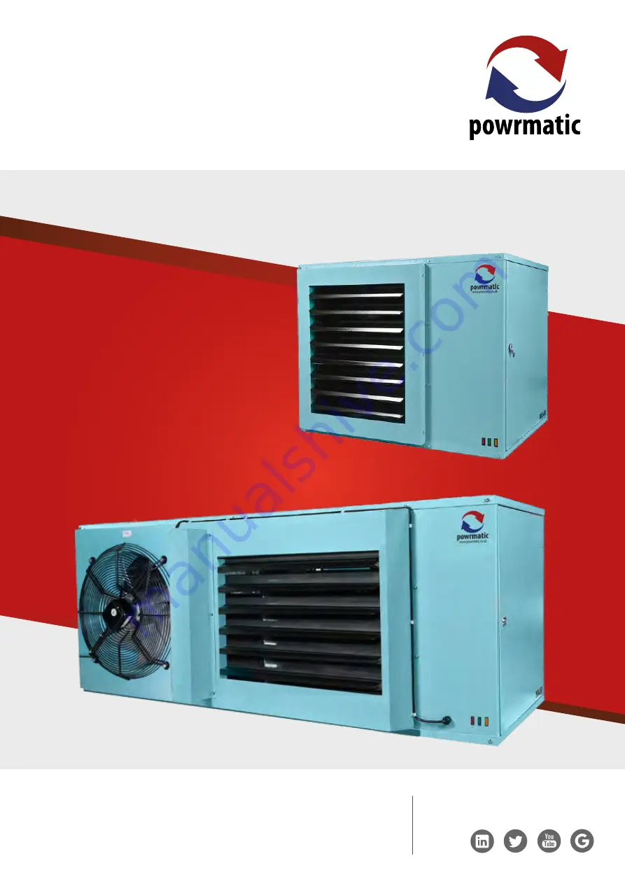
NVx Suspended Gas Unit Heater
User, Installation& Servicing Manual
Страница 1: ...p o w m a t i c c o u k 4 4 0 1 4 6 0 5 3 5 3 5 i n f o p o w r m a t i c c o u k Issue 6 4 Aug 2017 Industrial Commercial Heating Systems NVx Suspended Gas Unit Heater User Installation Servicing Ma...
Страница 2: ...wrmatic 3 The heater has been maintained on a yearly basis by a competent servicing company 4 The heater has been used in accordance with the manufacturers instructions 5 The correct specification fue...
Страница 3: ...up you deserve If you have any questions or concerns regarding this product please contact our Technical Support Team by calling 01460 53535 Title Section Contents Page User Instructions 4 Pre Install...
Страница 4: ...ault condition must be identified and rectified and the thermostat manually reset via the red high limit reset switch When the unit has cooled push the Red indicator switch inside the front panel to r...
Страница 5: ...ded primarily for heating commercial or industrial premises All variants with the exception of NVx EA units are for internal use only NVx heaters feature a closed combustion circuit and have an intern...
Страница 6: ...912 831 975 1140 Width mm 1000 1000 1000 1000 1000 1000 1325 1325 1950 1950 1950 Depth mm 892 925 925 925 905 925 941 941 925 941 941 Install Clearance NVx F Top mm 200 LH Side mm 200 RH Side mm 1000...
Страница 7: ...142 142 142 220 220 220 220 220 H mm 317 317 317 317 317 317 347 347 347 347 347 J mm 450 450 450 450 450 450 700 700 2 x 662 5 2 x 662 5 2 x 662 5 K mm 218 232 5 232 5 232 5 232 5 232 5 278 278 278...
Страница 8: ...F mm 487 631 798 G mm 220 220 220 H mm 347 347 347 J mm 2 x 662 5 2 x 662 5 2 x 662 5 K mm 278 278 278 L mm 1287 1350 1350 M mm 246 246 246 N mm 88 88 88 P mm 326 398 481 Q mm 188 207 207 NVx SF90 Du...
Страница 9: ...487 631 796 G mm 120 120 120 142 142 142 220 220 220 220 220 H mm 283 283 304 283 283 283 312 312 319 319 319 J mm 260 260 260 260 260 260 385 385 460 460 460 K mm 197 197 197 197 197 197 243 243 251...
Страница 10: ...40 760 760 912 760 912 831 975 1140 D mm 80 80 80 100 100 100 130 130 130 130 130 E mm 248 248 248 233 5 233 5 233 5 235 5 235 5 235 5 235 5 235 5 F mm 308 308 308 492 492 644 416 568 487 631 796 G mm...
Страница 11: ...317 317 317 317 317 347 347 347 347 347 J mm 450 450 450 450 450 450 700 700 2 x 662 5 2 x 662 5 2 x 662 5 K mm 218 232 5 232 5 232 5 232 5 232 5 278 278 278 278 278 L mm 835 835 835 835 835 835 835 8...
Страница 12: ...60 NVX05090DH 716 862 934 500 659 NVx 75 NVX06090DH 868 1015 934 630 659 NVx SF90 NVX07590DH 787 595 1566 560 659 NVx SF120 NVXSF12090DH 931 667 1566 700 659 NVx SF140 NVXSF14090DH 1096 746 1566 840...
Страница 13: ...NVx 30 40 NVx030 PLENUM 750 725 795 714 644 NVx 50 NVx050 PLENUM 750 725 947 866 644 NVx 60 NVx060 PLENUM 750 1020 795 714 939 NVx 75 NVx075 PLENUM 825 1020 947 866 939 NVx SF90 NVxSF090 PLENUM 900 1...
Страница 14: ...0 29 Injector Sizes Burner Pressures Natural Gas Group H G20 Net CV Hi 34 02MJ m Nominal Inlet Pressure 20mbar Minimum Inlet Pressure 17 5mbar High Fire Low Fire Injectors Burner Pressure Gas Rate Bur...
Страница 15: ...Input Nett Output Input Nett Output MODEL kW kW m s m h Pa dB A kg NVx15 F 16 4 15 0 8 22 7 3 0 42 1500 50 54 71 5 CCF 145 n a 106 5 NVx20 F 21 9 20 0 11 96 10 6 0 56 2020 50 52 71 5 CCF 177 n a 120...
Страница 16: ...d Light Industrial Environments and EN 61000 6 2 2005 Generic Immunity for Industrial Environments 1 3 2 Location Powrmatic NVx units are designed to operate within an ambient temperature range of 10...
Страница 17: ...al gas undertaking should be consulted at the installation planning stage in order to establish the availability of an adequate supply of gas An existing service pipe must not be used without prior co...
Страница 18: ...stallations Where NVx heaters are Installed in a plant room or an enclosure ie not within the heated space having combustion air ducted to the appliance and combustion products ducted to the outside a...
Страница 19: ...the air heater s is installed in a plant room the return air intake s and the warm air outlet s from the heater s must be fully ducted into and out of the plant room to avoid interference with the op...
Страница 20: ...at front of heater mm 200 C Top of heater mm 200 D Rear of heater dependent on flue system mm 400 E Recommended mounting heights floor level to underside of unit NVx15F 30F mm 2500 3000 NVx40F 140SFF...
Страница 21: ...oints be used as the final means of suspension Threaded drop rods must have lock nuts fitted that are tightened down onto the 10mm fixings in the heater If reducing noise levels is important the heate...
Страница 22: ...required see Section 1 2 5 Page 7 fit the mesh inlet plate behind the unused combustion air inlet hole 3 Apply silicon sealant and refit blanking plates as required to seal unused panel holes 2 2 2 G...
Страница 23: ...t the twin to concentric adaptor to the terminal section and then extend down to the heater using straight lengths Fit adjustable lengths as the final connection pieces to facilitate flue disconnectio...
Страница 24: ...odulating burner may require an inline condense flue drain if vertically flued due to the lower flue gas temperatures experienced when the heater is operating at low firing rates Exceptions may occur...
Страница 25: ...et is by a switched Neutral to the controls in the heater Reference must be made to Section 1 2 to ascertain the electrical loading of the unit s being installed so that cables of adequate cross secti...
Страница 26: ...ide optimum system efficiency and fuel savings Wiring drawings and instructions are supplied with the respective controller External Wiring The wiring terminals are located inside the electrical box b...
Страница 27: ...03 142466403 142466402 143000534 E F 2 2 3 3 4 4 5 5 6 6 NOTES Mains Input 230v 50Hz 1ph Supply For input power refer to Installation instructions Warning High voltages present at the ignition electro...
Страница 28: ...43100662 143000816 142400303 142466403 142466402 143000534 141366009 141366010 143016130 E F 2 2 3 3 4 4 5 5 6 6 NOTES Mains Input 230v 50Hz 1ph Supply For input power refer to Installation instructio...
Страница 29: ...662 143000816 142400303 142466403 142466402 143000534 141366009 141366010 Model specific Model specific 143100603 E F 2 2 3 3 4 4 5 5 6 6 NOTES Mains Input 230v 50Hz 1ph Supply For input power refer t...
Страница 30: ...electrode when the unit attemps to light D NC NO C N B C C 5 Core Cable Yel 0 5 Wh 0 5 Br 0 5 Blu 0 5 Br 0 5 Blu 0 5 Gry 0 75 Br 0 75 Blk 0 75 Yel 0 75 A J K Or 0 5 7 7 8 8 9 9 10 10 12 12 13 13 14 14...
Страница 31: ...eater operates in low fire 1 1 2 2 5 5 6 6 N Gry 0 5 Or 0 5 Blk 0 5 Wh 0 5 3 3 4 4 Br 0 75 Blu 0 75 Additional Wiring for Opional Items Modulation Burner Hi Lo Burner Downflow Unit Interconnecting Wir...
Страница 32: ...inter operation 2 6 5 Lighting the Air Heater NOTES On initial lighting of the heater s it may take some time to purge the internal pipe work of air IMPORTANT The internal pipe work of the appliance h...
Страница 33: ...ts 1 Set external controls to ensure that the main burner is off Open the side access door Connect a pressure gauge to the burner pressure test point on the multifunctional control 2 Set external cont...
Страница 34: ...t joint using a leak detection fluid Replace access panel Cover Lever point Hexagonal adjustment screw for maximum pressure setting Internal slotted adjustment screw for minimum pressure setting Hi Lo...
Страница 35: ...hen P1 is set at 100 fully clockwise maximum power 165mA 22VDC is provided to the modulation coil with a 10VDC input control signal When P1 is set at 50 fully anticlockwise maximum power 165mA 22VDC i...
Страница 36: ...against the heater Ensure that an access tower or equivalent is used NOTE The access door to the controls section may be removed to improve access Open the door to 90 remove the earth cable at the bot...
Страница 37: ...ible gas connection has been used go to step 2 otherwise unscrew the union nut situated immediately downstream of the gas service valve 3 Remove the burner heat shield 3 screws 4 Release the inlet con...
Страница 38: ...30 C 122 F 50 C 212 F 100 C 1 Undo cover retaining screw 2 Squeeze the sides of the cover and remove cover by pulling forward 3 Release wiring from clamp terminals by pushing a small screwdriver into...
Страница 39: ...ement in reverse order refitting the sensing tube to the negative or L tapping on the pressure switch Adjust setting to that of the old pressure switch 2 7 6 7 Control Box 1 Unplug all the electrical...
Страница 40: ...reset Press Red reset switch internal panel when unit is cool If it will not reset when cold check for for 230V between terminals 9 11 on the limit interface board Check faulty limit stat Gas Electric...
Страница 41: ...nuity slightly reduce APS set point Check for 230V between terminals 12 N of the terminal strip Absent Replace motor capacitor or fan motor assembly Check connections overloads etc as applicable Absen...
Страница 42: ...120SF 140SF 141378715 KIT Ignition Electrode 15 75 90SF 140SF 142423002 142400004 Rectification Flame Sensor Probe All 142423003 Burner 15 75 90SF 140SF 142400240 142400241 Fan Limit Thermostat L4064...
Страница 43: ...Mounting Brackets 60 75 60 75 140201505 NVX6075EXH SP Exhaust Fan Exhaust Fan c w Mounting Brackets 90SF 140SF 90SF 140SF 140201506 NVX90140EXH SP Main Air Fan NVx F 15 20 25 30 40 50 90SF 60 75 120SF...
Страница 44: ...Tel 01460 53535 Fax 01460 52341 Every effort is made to ensure accuracy at time of going to press However as part of continued product improvement we reserve the right to alter specification without p...