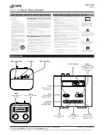
CONTROLS
AND
FEATURES
OVERVIEW
1. INPUT:
This is where you may plug in microphones, instruments, keyboards, drum
machines and other audio devices.
2. MONITOR OUT:
This is a Balanced XLR or Unbalanced TRS 1/4-inch line out used to
send a summed mix of the INPUTS to other devices such as mixers, powered speakers,
powered monitors or recording devices.
3. MAIN OUT:
This is a Balanced XLR or Unbalanced TRS 1/4-inch line out used to send a
summed mix of the INPUTS to other devices such as mixers, powered speakers,powered
monitors or recording devices.
4. EFFECTS:
Use these controls to adjust the volume level of Digital Reverb effects for this
individual channel.
6. LOW:
Determines the emphasis of bass frequencies. Turning this knob clockwise creates
a deeper, warmer tone. If you need a brighter sound, reduce the bass by turning
counterclockwise.
8. VOLUME:
Use these controls to adjust the volume level of each channel and the relative
balance between them to the MAIN out connectors.
NOTE
:
HIGH, LOW, and VOLUME controls are vertically aligned with the INPUTS they affect.
7. MONITOR:
Use these controls to adjust the MONITOR volume level of each channel and
the relative balance between them to the MONITOR out connectors.
5. HIGH:
Turned clockwise, this control increases treble frequencies to produce clearer,
crisper sound. Turn counterclockwise to make the sound softer and less bright.
9. EFFECTS MASTER:
Use this control to adjust the overall volume of the Digital Reverb to
the MAIN Outputs.
10. MONITOR MASTER:
Use these controls to adjust the overall MONITOR volume level of
each channel and the relative balance between them to the MONITOR out connectors.
11
.
MASTER:
Use this controls to adjust the overall volume of the mixer.
12
.
POWER:
This switch activates power to the mixer.
13.
POWER INDICATOR LIGHT:
Indicates that the power switch is in the “ON” position.
When light is illuminated, the unit is ON.
14 POWERLINK:
Use the POWERLINK circuit to link multiple PW systems using standard
microphone cables. This feature combines the channels in all linked units while each
MASTER control operates independently.
.
IN:
This balanced XLR Jack connects to the POWERLINK OUT from another PW unit using a
standard mic cable. Channels from both PW units are summed together. Use the channel
volume controls to balance the mix between channels (If a channel is not used turn the
volume all the way down). MASTER controls the overall level of mix sent to MAIN OUT of
this PW6EFX. It does not affect the volume of linked units.
OUT:
This balanced XLR Jack connects to the POWERLINK IN from another PA unit using a
standard mic cable. Channels from both units are summed together. Use the channel
volume controls to balance the mix between channels (If a channel is not used turn the
volume all the way down). MASTER volume controls the overall mix through this PW6EFX.
It does not affect the volume of linked units. This jack may also be used to connect the
PW6EFX unit to a power amp with a balanced line.
1
1
2
3
4
5
6
7
8
9 10
11 12 13
14
15 POWER INPUT:
Connect the included 18Vdc wall adapter here.
.
15
Содержание PW6EFX
Страница 4: ...BLOCK DIAGRAM PW6EFX...


