background image

9

Section

INSTALLATION

2-1.  INTRODUCTION

This section contains unpacking, inspection, and installation instructions and recommendations for
the Model G3L-800-25-001 Multichannel Power Amplifier.  Carefully read all material in this section
prior to equipment unpacking or installation.  Also read and review the operating procedures in
Section 3 prior to installing the equipment.  It is important that the licensee perform these tasks
correctly and in good faith.  If applicable, carefully read Parts 73 and 74 of the Federal
Communications Commission (FCC) rules to determine how they apply to your installation.  DON'T
TAKE CHANCES WITH YOUR LICENSE.

2-2.  ELECTRICAL SERVICE RECOMMENDATIONS

Powerwave Technologies recommends that proper AC line conditioning and surge suppression be
provided on the primary AC input to the +27 Vdc power source.  All electrical service should be
installed in accordance with the National Electrical Code, any applicable state or local codes, and
good engineering practice.  Special consideration should be given to lightning protection of all
systems in view of the vulnerability of most transmitter sites to lightning.  Lightning arrestors are
recommended in the service entrance.  Straight, short ground runs are recommended.  The
electrical service must be well grounded.

Each amplifier system should have its own circuit breaker, so a failure in one does not shut off the
whole installation.  Circuit breakers should be thermal type, capable of handling the anticipated
inrush current, in a load center with a master switch.

2-3.  UNPACKING AND INSPECTION

This equipment has been operated, tested and calibrated at the factory.  Carefully open the
container(s) and remove the amplifier module(s).  Retain all packing material that can be
reassembled in the event that the unit must be returned to the factory.

CAUTION

Exercise care in handling equipment
during inspection to prevent damage
caused by rough or careless handling.

Visually inspect the amplifier module for damage that may have occurred during shipment.  Check
for evidence of water damage, bent or warped chassis, loose screws or nuts, or extraneous packing
material in the connector.  If the equipment is damaged, a claim should be filed with the carrier
once the extent of any damage is assessed.  We cannot stress too strongly the importance of
IMMEDIATE careful inspection of the equipment and the subsequent IMMEDIATE filing of the
necessary claims against the carrier if necessary.  If possible, inspect the equipment in the
presence of the delivery person.  If the equipment is damaged, the carrier is your first area of
recourse.  If the equipment is damaged and must be returned to the factory, write or phone for a
return authorization.  Powerwave may not accept returns without a return authorization.  Claims for
loss or damage may not be withheld from any payment to Powerwave, nor may any payment due
be withheld pending the outcome thereof.  WE CANNOT GUARANTEE THE FREIGHT
CARRIER'S PERFORMANCE

2

Содержание G3L-800-25-001

Страница 1: ...SERVICE MANUAL MULTICHANNEL POWER AMPLIFIER G3L 800 25 001 869 894 MHz 25 WATTS AVERAGE POWER 15 JANUARY 1999 Powerwave Technologies Inc Tel 949 757 0530 2026 McGaw Avenue Fax 949 757 0941 Irvine CA 92614 Web Site www powerwave com ...

Страница 2: ...arm Control and RF Connector 2 2 2 6 Amplifier Module RS 232 Connector 2 4 Section 3 Operating Instructions 3 1 Introduction 3 1 3 2 Initial Start Up and Operating Procedures 3 1 Section 4 Principles of Operation 4 1 Introduction 4 1 4 2 RF Input Signal 4 1 4 3 RF Output Load 4 1 4 4 Amplifier Functional Description 4 1 4 4 1 Predriver Amplifier 4 1 4 4 2 Three Stage Driver Amplifier 4 1 4 4 3 Mai...

Страница 3: ...o 1 1 G3L 800 25 001 Amplifier Showing Front Panel 1 3 1 2 G3L 800 25 001 Amplifier Showing Rear Panel 1 4 2 1 Power Alarm Control and RF Connector D Subminiature 21WA4 Male Connector 2 3 2 2 RS 232 Connector on Rear of G3L 800 25 001 Module 2 4 4 1 G3L 800 25 001 Multi Channel Power Amplifier Functional Block Diagram 4 2 5 1 G3L 800 25 001 Amplifier Test Setup Diagram 5 3 LIST OF TABLES Table Pag...

Страница 4: ...4 5 3 Multichannel Power Amplifier Test Data Sheet 5 4 6 1 Troubleshooting 6 1 ...

Страница 5: ... contained module with EMI containment for use in both indoor and outdoor North American cellular base stations The G3L 800 25 001 accepts single channel and transmit voice RF signals The G3L 800 25 001 uses an internally generated tone to optimize its performance The system operating band A or B is externally provided to the G3L 800 25 001 so that it knows where the tone frequency is going to be ...

Страница 6: ...ale D sub RF Output Connector 21WA4 male D sub Phase 180 5 degrees measured at 880 MHz 25 ºC any power level Phase Tracking 10 degrees from 25 ºC across specified temperature range IMD 60 dBc 8 carriers continuous phase random equal carrier spacing of 1 25 MHz Any power up to maximum average output power Output Return Loss 18 dB at any power level Harmonic Output 45 dBc at any number of carriers a...

Страница 7: ...7 Figure 1 1 G3L 800 25 001 Amplifier Showing Front Panel 15 57 2 64 13 82 MINOR MAJOR ...

Страница 8: ...8 Figure 1 2 G3L 800 25 001 Amplifier Showing Rear Panel 21WA4 Male D Sub Connector 21WA4 D Sub Connector ...

Страница 9: ... off the whole installation Circuit breakers should be thermal type capable of handling the anticipated inrush current in a load center with a master switch 2 3 UNPACKING AND INSPECTION This equipment has been operated tested and calibrated at the factory Carefully open the container s and remove the amplifier module s Retain all packing material that can be reassembled in the event that the unit ...

Страница 10: ...imary power and negative primary power to the subrack Tighten the subrack power connections 8 Place power on off switch on the amplifier front panel in the off down position Insert the plug in amplifier module s in the subrack Tighten top and bottom thumbscrews 9 Check your work before applying DC voltage to the system Make certain all connections are tight and correct 10 Measure primary DC input ...

Страница 11: ...R A HIGH FLOAT FOR A LOW 8 RACK A0 ADDRESS IN LSB GROUND PIN FOR A HIGH FLOAT FOR A LOW 9 NOT USED 10 AMP A2 ADDRESS IN MSB GROUND PIN FOR A LOW FLOAT FOR A HIGH 11 FAN FAIL INPUT GROUND PIN FOR A LOW FLOAT FOR A HIGH 12 AMP A1 ADDRESS IN MiddleSB GROUND PIN FOR A LOW PASS FLOAT FOR A HIGH FAIL 13 NOT USED 14 AMP A0 ADDRESS IN LSB GROUND PIN FOR A LOW FLOAT FOR A HIGH 15 NOT USED 16 NOT USED 17 NO...

Страница 12: ...TRODUCTION This section contains operating instructions for the Multicarrier Amplifier 3 2 INITIAL START UP AND OPERATING PROCEDURES To perform the initial start up proceed as follows 1 Double check to ensure that all input and output cables are properly connected CAUTION Before applying power make sure that the input and output of the amplifier are properly terminated at 50 ohms Do not operate th...

Страница 13: ...e 25 MHz frequency band from 869 MHz to 894 MHz at an output power of 25 watts Each amplifier is a self contained module and is functionally independent of any other amplifier modules in the system Each amplifier module has an alarm board that monitors the amplifier performance If a failure or fault occurs in an amplifier module it is transmitted to the host system via the D subminiature 21Wa4 con...

Страница 14: ...roximately 13 5 dB of gain in the 25 MHz frequency band from 869 MHz to 894 MHz The amplifier operates on 27 Vdc 4 4 2 THREE STAGE DRIVER AMPLIFIER The input of the amplifier employs three stages of class AB amplification which provide approximately 32 dB of gain in the 25 MHz frequency band from 869 MHz to 894 MHz The amplifier operates on 27 Vdc ...

Страница 15: ...are output via a 21WA4 D sub connector on the module for subsequent remote monitoring 4 4 5 LOOP CONTROL CIRCUIT The primary function of the loop control circuit is to reduce the spurious emissions of the RF signal at all amplifier stages The loop control circuit controls internal amplifier parameters of all amplifier stages thereby optimizing spurious emissions 4 5 AMPLIFIER MODULE COOLING Each a...

Страница 16: ...le 5 1 Table 5 1 also lists the intervals at which the tasks should be performed Table 5 1 Periodic Maintenance TASK INTERVAL ACTION Inspection Cables and Connectors 12 Months I In ns sp pe ec ct t s si ig gn na al l a an nd d p po ow we er r c ca ab bl le es s f fo or r f fr ra ay ye ed d i in ns su ul la at ti io on n C Ch he ec ck k R RF F c co on nn ne ec ct to or rs s t to o b be e s su ur re...

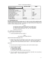
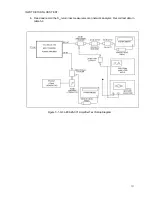
Страница 17: ...n amplifier with a 25 MHz band from 869 MHz to 894 MHz Select evenly spaced F1 F2 F3 and F4 frequencies that cover the instantaneous bandwidth of your system 5 4 1 AMPLIFIER PERFORMANCE TEST To perform the test proceed as follows 1 Connect test equipment as shown in figure 5 1 NOTE Do not apply any RF signals at this time AMPLIFIER SPURIOUS EMISSIONS TEST 2 With the RF input signal to the amplifie...

Страница 18: ...18 INPUT RETURN LOSS TEST 6 Read and record the S11 return loss measurement on network analyzer Record test data in table 5 3 Figure 5 1 G3L 800 25 001 Amplifier Test Setup Diagram ...

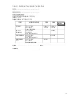
Страница 19: ...ce Impedance 50 Ohms VSWR 1 2 1 Supply Voltage 27 Vdc 0 1 Vdc TEST SPECIFICATION MIN MAX DATA RF Gain Vcc 27 Vdc PO 25 W Freq 880 MHz Table 1 1 0 5 dB Table 1 1 0 5 dB Spurious Emissions Vcc 27 Vdc PO 25 W 869 894 MHz Band 60 dBc Gain Flatness Vcc 27 Vdc PO 25 W 869 894 MHz Band 0 5 dB Input Return Loss Vcc 27 Vdc PO 25 W 869 894 MHz Band 12 dB PASS FAIL Tested by ...

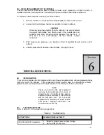
Страница 20: ...er to pull module out of subrack 4 Install replacement in reverse order of steps 1 through 3 above TROUBLESHOOTING 6 1 INTRODUCTION This section contains a list of problems which users have encountered and a few suggested actions that may correct the problem If the suggested corrective action does not eliminate the problem please contact your Powerwave field representative or the factory for furth...

Страница 21: ...g equipment to the factory for service Please contact our Customer Service Department at 949 757 0530 to obtain this number Failure to obtain this RMA number may result in considerable delays in receiving repair service 6 3 2 Repackaging for Shipment To ensure safe shipment of the amplifier it is recommended that the package designed for the amplifier be used The original packaging material is reu...

Отзывы: