5
ASSEMBLY
BACKSTOP
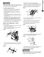
Refer to Figure 10
The backstop is a surface to sand against.
The backstop can be removed for polishing and contour
sanding.
• Remove screws and washers securing backstop. Place
screws, washers and backstop in a safe place for future
use.
Figure 10
Screws and
Washers
Backstop
DUST PORT OPTIONS
The dust ports can be easily connected to a dust
collection system with a large diameter shop vacuum
hose.
Sanding operations are inherently dusty. This sander
is equipped with a 1-13/16" OD disc dust port and a
1-3/4" OD belt dust port to help minimize the amount
of dust escaping into the surrounding air. Attach the
dust collection system vaccum hose to the dust chute.
NOTE: The use of a dust collection system is strongly
recommended when using the belt/disc sander. Use of a
mask or respirator is still recommended even when using
a dust collection system.
MOUNTING THE SANDER TO WORK
SURFACE
Refer to Figure 11
CAUTION
Properly mount the sander to a workbench or stand if
during operation the sander has the tendency to tip over,
slide or walk on the work surface.
• Remove the four rubber feet from the sander.
• Position the sander in place on the work surface. Mark
the work surface using the holes in the sander base as
a template. Remove the sander from the work surface.
• Drill holes in the work surface at the marks.
• Secure the sander to the work surface using long bolts,
flat washers and hex nuts (not supplied) as shown.
NOTE: Bolts should be inserted from the top of the
sander and secured underneath the work surface with
flat washers, lock washers and hex nuts. A rubber
washer should be placed between the sander and the
workbench.
Figure 11
Bolt
Workbench
Rubber
Washer
Flat Washer
Hex Nut
Flat Washer
Sander
POWER SOURCE
WARNING
Do not connect to the power source until the machine is
completely assembled.
The machine is wired for 120 volts, 60 HZ alternating
current. Before connecting the machine to the power
source, make sure the switch is in the “OFF” position.
Running the unit on voltages which are not within range
may cause overheating and motor burn-out. Heavy loads
require that voltage at motor terminals be no less than the
voltage specified on nameplate.
• Power supply to the motor is controlled by a locking
rocker switch. Remove the key to prevent unauthorized
use.
GROUNDING INSTRUCTIONS
WARNING
Improper connection of equipment grounding conductor
can result in the risk of electrical shock.
• The machine should be grounded while in use to protect
operator from electrical shock.
• In the event of an electrical short circuit, grounding
reduces the risk of electrical shock by providing an
escape wire for the electric current.
• This machine is equipped with an approved 3-conductor
cord rated at 150V and a 3-prong grounding type plug
for your protection against shock hazards.
• Grounding plug should be plugged directly into a
properly installed and grounded 3-prong grounding-type
receptacle, as shown (Figure 12).
• The plug must be plugged into an outlet that is properly
installed and grounded in accordance with all local
codes and ordinances.
• Check with a qualified electrician or service personnel if
these instructions are not completely understood or if in
doubt as to whether the tool is properly grounded.


