background image


POWX0761 

EN


Copyright © 2008 VARO 

P a g e

 | 

7


www.varo.com 

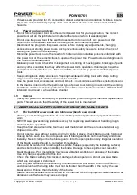
  If devices are provided for the connection of dust extraction and collection facilities, ensure 

these are connected and properly used. Use of these devices can reduce dust related 
hazards.  

5.4 

Power tool use and care  

  Do not force the power tool. Use the correct power tool for your application. The correct 

power tool will do the job better and safer at the rate for which it was designed. 

  Do not use the power tool if the switch does not turn it on and off. Any power tool that 

cannot be controlled with the switch is dangerous and must be repaired. 

  Disconnect the plug from the power source before making any adjustments, changing 

accessories, or storing power tools. Such preventive safety measures reduce the risk of 
starting the power tool accidentally. 

  Store idle power tools out of the reach of children and do not allow persons unfamiliar with 

the power tool or these instructions to operate the power tool. Power tools are dangerous in 
the hands of untrained users. 

  Maintain power tools. Check for misalignment or sticking of moving parts, breakage of parts 

and any other condition that may affect the power tool’s operation. If damaged, have the 
power tool repaired before use. Many accidents are caused by poorly maintained power 
tools. 

  Keep cutting tools sharp and clean. Properly maintained cutting tools with sharp cutting 

edges are less likely to stick and are easier to control. 

  Use the power tool, accessories and tool bits etc., in accordance with these instructions and 

in the manner intended for the particular type of power tool, taking into account the working 
conditions and the work to be performed. Use of the power tool for operations different from 
intended could lead to a hazardous situation. 

5.5 

Service 

  Have your power tool serviced by a qualified repair person using only identical replacement 

parts. This will ensure that the safety of the power tool is maintained. 

6  ADDITIONAL SAFETY INSTRUCTIONS FOR TABLE SAWS 

6.1 

For both Mitre saw mode and table saw (bench saw) mode: 

  Wear eye and hearing protection. Other suitable personal protective equipment should be 

worn.  

  NEVER wear gloves during operation except for replacing saw blades or handling rough 

material before operation. 

  Keep the floor area around the tool level, well maintained and free of loose materials e.g. 

chips and cut-offs. 

  Do not operate saw without guards and riving knife in place. Check blade guards for proper 

closing before each use. Do not operate saw if blade guards do not move freely and close 
instantly. Never clamp or tie the blade guards into the open position. Any irregular operation 
of the blade guards should be corrected immediately. 

  Clean and be careful not to damage the spindle, flanges (especially the installing surface) 

and hex bolt before or when installing the blade. Damage to these parts could result in 
blade breakage. Poor installation may cause vibration/ wobbling or slippage of the blade. 
Use only flanges specified for this tool.    

  Check the blade carefully for cracks or damage before operation. Do not use saw blade 

which are damaged or deformed.   

  Use only saw blades recommended by the manufacturer and which conform to EN847-1, 

and observe that the riving knife must not be thicker than the width of the cut by the saw 
blade and not thinner than the body of the blade.    

  Always use accessories recommended in this manual. Use of improper accessories such as 

abrasive cut-off wheels may cause an injury.   

All manuals and user guides at all-guides.com

Содержание POWX0761

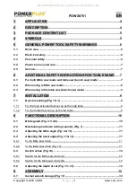
Страница 1: ...STALLATION 9 7 1 Bench mounting Fig 1 3 9 7 1 1 For the fully extended feet set up as the high table 9 7 1 2 For the folded feet set up as the low table 9 8 FUNCTIONAL DESCRIPTION 10 8 1 Blade guard F...

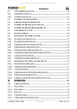
Страница 2: ...he riving knife Fig 44 16 9 9 5 Removing the lower blade guard Fig 45 16 9 9 6 Locking the tool head at fully lowered position Fig 46 16 9 9 7 Turning over the tool Fig 48 16 9 9 8 Installing the top...

Страница 3: ...ge 20 10 2 7 Use of Mitre gauge Fig 64 20 10 2 8 Auxiliary wood facing Mitre gauge Fig 65 20 10 2 9 Carrying tool Fig 66 21 11 MAINTENANCE 21 11 1 Adjusting the cutting angle 21 11 1 1 Mitre angle 21...

Страница 4: ...ton 25 Switch lever 26 On button 27 Off button 28 Stopper pin 29 Socket wrench 30 Wrench holder 31 Feet 32 33 34 Shaft lock 35 Lifting lever 36 Saw blade 37 Blade case 38 Arrow 39 Outer flange 40 Inne...

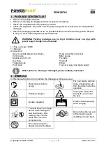
Страница 5: ...s Vertical vise Socket wrench 13 3 Dust bag Triangular rule Push stick Ruler assembly rip fence Miter gauge Fix plate Hex bolt Elbow Top cover assy top blade guard When parts are missing or damaged pl...

Страница 6: ...g the power tool Keep cord away from heat oil sharp edges or moving parts Damaged or entangled cords increase the risk of electric shock When operating a power tool outdoors use an extension cord suit...

Страница 7: ...e performed Use of the power tool for operations different from intended could lead to a hazardous situation 5 5 Service Have your power tool serviced by a qualified repair person using only identical...

Страница 8: ...other parts of the workpiece from the cutting area whilst the tool is running and the saw head is not in the rest position Stop operation immediately if you notice anything abnormal Turn off tool and...

Страница 9: ...perly by not releasing the workpiece until you have pushed it all the way past the blade and by not ripping 6 workpiece that is twisted or warped or does not have 6 straight edge to guide along the fe...

Страница 10: ...de guards NEVER USE THE TOOL IF THE LOWER BLADE GUARD SPRING OR THE TOP BLADE GUARD ARE DAMAGED FAULTY OR REMOVED except for the note below DOING SO IS HIGHLY DANGEROUS AND CAN CAUSE SERIOUS PERSONAL...

Страница 11: ...and thin workpiece To use the tool with the lower limit move the stopper end clockwise Use in this position is proper to cut a thick workpiece 8 3 Adjusting the Mitre angle Fig 9 10 Loosen the clampi...

Страница 12: ...ting knob Turn the cutting depth adjusting knob clockwise to raise the blade or counterclockwise to lower it WARNING Use a shallow depth setting when cutting thin materials in order to obtain a cleane...

Страница 13: ...aced in the blade guard Fig 22 23 CAUTION The ring 30 mm in outer diameter is factory installed between the inner and outer flanges Return the lower blade guard 8 to its original position Lower the ha...

Страница 14: ...figure To change from the pattern A or B to the pattern C or D or in adverse case remove the square nut and clamping screw 47 from the rip fence holder then position the clamping screw 47 and square n...

Страница 15: ...and tighten the clamping screw to secure the vise rod Position the vise arm according to the thickness and shape of the workpiece and secure the vise arm by tightening the clamping screw If the screw...

Страница 16: ...uardfrom the table by loosening the clamping screw 9 9 6 Locking the tool head at fully lowered position Fig 46 After setting up the riving knife in position for table saw mode pull the stopper in the...

Страница 17: ...ning riving knife Fig 51 The position of riving knife Fig 51 A should be changed as follows 1 Loosen the clamping nut and hold the lower blade guard A using its lug by hand Fig 51 B 2 While holding th...

Страница 18: ...returning the blade to its fully elevated position 10 1 2 Mitre cutting Refer to the previously covered Adjusting the Mitre angle 10 1 3 Bevel cut Loosen the lever and tilt the saw blade to set the be...

Страница 19: ...ot bend or twist it while feeding If the workpiece is bent or twisted dangerous kickbacks may occur NEVER withdraw the workpiece while the blade is running If you must withdraw the workpiece before co...

Страница 20: ...stick will strike the blade guard Use the auxiliary fence and push block Attach the auxiliary fence to the rip fence with two C clamps Fig 61 Feed the workpiece by hand until the end is about 25 mm fr...

Страница 21: ...the guide fence using a triangular rule trysquare etc Then securely tighten the four adjusting bolts on the sub arm from the underside of the table Make sure that the pointer points to 0 on the Mitre...

Страница 22: ...aintenance or adjustment should be performed by an Authorized Service Centers always using original replacement parts 11 4 Service Only qualified specialist personnel and original replacement parts sh...

Страница 23: ...aterial or production flaws It does not include defective parts subject to normal wear tear such as bearings brushes cables plugs or accessories such as drills drill bits saw blades etc damage or defe...

Страница 24: ...ation of the apparatus voids this declaration European Directives and their amending directives 2006 95 EC The Low Voltage Directive 2004 108 EC The Electromagnetic Compatibility Directive 98 37 EC Th...

Отзывы: