
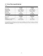


14
Figure 7-4
Figure 7-5
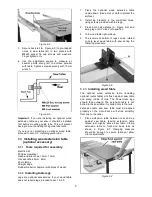
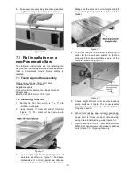
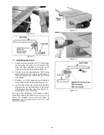
7.3
Installing back rail
1. Locate the back rail which is 2" x 2" with holes
running along one side only. The height of the
back rail when attached to the saw is not
critical, but it should be parallel to table top.
2. Position back rail approximately 9/16" below
table surface, with the ends even with those of
front rail (Figure 7-6). Hold back rail to saw
with clamps.
3. Drill 9mm (or 11/32”) holes into lip of saw table
using holes in back rail as guide (Figure 7-7).
4. Insert socket head cap screws with washers
through back rail and saw table, and secure
with washers and hex nuts. See Figure 7-8.
Finger-tighten only at this time
.
The rest of the installation is the same as with a
Powermatic table saw. Refer back to
sect. 6.4
to
mount the optional wood extension table (if
applicable) and the guide tube in
sect. 6.5
, and
proceed from there.
Figure 7-6
Figure 7-7
Figure 7-8


