background image


Operating Instructions and Parts Manual 

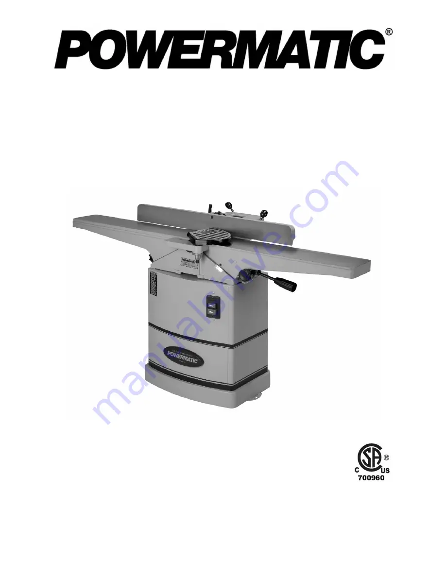
6-inch Woodworking Jointer 

Models 54A and 54HH 


54A (1791279DXK) serial # 8040543557 and up 
54HH (1791317K) serial # 8010540313 and up 


WMH TOOL GROUP, Inc. 

2420 Vantage Drive 
Elgin, Illinois 60123 

Part No. M-1791279DX


Ph.: 800-274-6848 

Revision C  06/08 

www.powermatic.com 

Copyright © 2008 WMH Tool Group, Inc. 

Содержание 54A

Страница 1: ...er Models 54A and 54HH 54A 1791279DXK serial 8040543557 and up 54HH 1791317K serial 8010540313 and up WMH TOOL GROUP Inc 2420 Vantage Drive Elgin Illinois 60123 Part No M 1791279DX Ph 800 274 6848 Revision C 06 08 www powermatic com Copyright 2008 WMH Tool Group Inc ...

Страница 2: ...or examination postage prepaid to a location designated by us For the name of the location nearest you please call 1 800 274 6848 You must provide proof of initial purchase date and an explanation of the complaint must accompany the merchandise If our inspection discloses a defect we will repair or replace the product or refund the purchase price at our option We will return the repaired product o...

Страница 3: ...ing Cutterhead Knives Model 54A only 17 Replacing Knives Model 54A only 19 Setting Knives for Rabbeting and Nicks Model 54A only 20 Replacing or Rotating Knife Inserts Model 54HH only 20 Determining Correct Table Height 21 Hand Placement 23 Direction of Grain 23 Surfacing 24 Jointing 24 Beveling 25 Skewing Shear Cutting 25 Rabbet Cuts Straight Knife only 26 Push Blocks 26 Blade Care 26 Cutterhead ...

Страница 4: ...nd other masonry products Arsenic and chromium from chemically treated lumber Your risk of exposure varies depending on how often you do this type of work To reduce your exposure to these chemicals work in a well ventilated area and work with approved safety equipment such as face or dust masks that are specifically designed to filter out microscopic particles 10 Do not operate this machine while ...

Страница 5: ...hine until the cutterhead comes to a complete stop 31 Always use a hold down or push block when surfacing stock less than 12 inches long or 3 inches wide or 3 inches thick 32 Do not perform jointing operations on material shorter than 8 narrower than 3 4 or less than 1 4 thick 33 The hands must never be closer than 3 inches to the cutterhead see Figure at right 34 Never apply pressure to stock dir...

Страница 6: ...ossibly even death On Off Switch Padlock The jointer is equipped with a push button switch that will accept a safety padlock not included To safeguard your machine from unauthorized operation and accidental starting by young children the use of a padlock is highly recommended see figure at right A padlock Stock No 709012 A is available from your local authorized WMH distributor or by calling WMH a...

Страница 7: ...4 x 66 Table support dove tailed ways dove tailed ways Cutterhead Style straight w quick set knives helical Knives 3 double edged 40 four sided inserts Cutterhead Speed RPM 6000 6000 Cuts per Minute 18 000 not applicable Cutting capacity in 1 2 x 6 1 2 x 6 Blade Size in 6 1 16 x 3 4 x 5 64 0 10T x 0 59 x 0 59 Switch push button push button Fence size overall in 4 x 38 4 x 38 Fence tilt degrees 45 ...

Страница 8: ... with Mounting Hardware 1 Dust Chute with Mounting Hardware Main Unit Carton 1 Jointer Assembly 1 Fence Assembly 1 Pulley Cover 1 Belt 1 Cutterhead Guard 2 Push Blocks 1 Fence Handle 1 Hardware Bag Contents of Hardware Bag Shown full scale in Figure 1 4 1 4 20 x 1 2 Pan Head Screws A 3 3 8 x 5 8 Spring Washers B 4 1 4 20 x 1 2 Flat Washers C 3 Lock Bolts D Tools Included Model 54A 1 8 10mm Open En...

Страница 9: ...tective coating from all machined surfaces of the jointer Do NOT use an abrasive pad Do not use gasoline acetone or lacquer thinner as these may damage painted surfaces 4 Apply a thin layer of paste wax to the bright surfaces of the fence and tables to prevent rust Alternatively white talcum powder rubbed in vigorously once a week with a blackboard eraser will fill any casting pores and form a moi...

Страница 10: ...C clockwise loosens the fence assembly permitting you to slide the assembly back and forth The hex nuts may need to be readjusted to allow the fence to slide back and forth handle clockwise position and still sufficiently secure the fence lock handle positioned as shown in C When the locking screw A is tightened the fence should be secure Installing the Drive Belt Referring to Figure 6 1 Place V b...

Страница 11: ...d from the top and hold 3 Insert the guard post into hole in table Make sure that the spring inside the spring knob B engages the slot in guard post If needed slightly turn the knob until the guard seats itself 4 Thread the screw C back into the guard post 5 Check for proper operation The cutterhead guard A must return fully to the fence when released If guard does not return fully pull guard appl...

Страница 12: ...our Woodworking Jointer is ready to run at 115 volt operation This Jointer when wired for 115 volt is intended for use on a circuit that has an outlet and a plug that looks like the one illustrated in A A temporary adapter which looks like the adapter shown in B may be used to connect this plug to a two pole receptacle if a properly grounded outlet is not available Figure 11 The temporary adapter ...

Страница 13: ...5 degrees 1 Loosen the lock handle B 2 Adjust the fence to the desired level down to 45 degrees Or you can place your reference piece on the table and against the fence and adjust the fence until the angle of the fence matches the bevel of your gauge piece 3 Tighten lock handle B To tilt fence backward The fence can be tilted backward up to 45 that is for a total included angle of 135 from table s...

Страница 14: ...s the stop bolt F and turn the stop bolt until the fence is square to the table 7 Tighten the lock nut D to secure the stop bolt F which retains the setting 8 Tighten the lock handle B 45º Forward Stop Adjustment Position the fence tilt lever E Fig 14 toward the operator The 45 degree forward stop is controlled by the cap screw G Fig 14 The adjustment is done the same way as for the 90 degree stop...

Страница 15: ...e depth of cut should never exceed 1 8 except for rabbetting operations Helpful Hint Occasionally you will find that you cannot set the coarse adjustment all the way up to zero or all the way down to 1 2 on the Depth of Cut scale Figure 17 when raising or lowering the handle C Fig 16 When this happens With the lock knob B Fig 16 unlocked rotate the height adjustment handle C Fig 16 a few times the...

Страница 16: ...ightening the jam nuts with the 10mm wrench Outfeed Table Height Adjustment When you receive the jointer the knives have been pre set at the factory However the height and parallelism of the knives with the outfeed table should be checked and any needed adjustments made before putting the jointer into operation Adjust the height of the outfeed table as follows 1 Disconnect jointer from power sourc...

Страница 17: ...ed to the Setting Cutterhead Knives section to verify that all three knives are at the correct height and parallel to the outfeed table For the model 54HH proceed to Replacing or Rotating Knife Inserts on page 20 Setting Cutterhead Knives Model 54A only Note Before setting knives for the 54A Jointer the Outfeed Table Height Adjustment should be done to ensure the proper knife height in relation to...

Страница 18: ...g screws to permit adjustment of the cam described in the next step Important Always keep the cam locking screws snug enough so that the cam can t rotate freely This is especially important for when the cam is rotated counterclockwise since this action will cause the cam locking screw to loosen further 8 Using an 8mm hex wrench adjust the cam see Figure 25 This is a very sensitive adjustment Start...

Страница 19: ... new knife or unused edge of the old knife back onto the cutterhead D 4 Replace the gib B and screws A Finger tighten only at this time 5 Press against the cutting edge of the knife at the center of the blade with a piece of wood DO NOT USE FINGERS This is to ensure that the cam is making proper contact with the knife 6 Snug the inside two screws then the outside two screws 7 Release the piece of ...

Страница 20: ...r a fresh edge and re install it Use the two provided star point screwdrivers to remove the knife insert screw See Figure 28 Use one of the screwdrivers to help hold the cutterhead in position and the other to remove the screw It is advisable to rotate all inserts at the same time to maintain consistent cutting However if one or more knife inserts develops a nick rotate only those inserts that are...

Страница 21: ...ore putting the jointer into operation The outfeed table and cutterhead knives Model 54A only are correctly adjusted when all three blades are parallel to the outfeed table and all three blades are set at the same height in the cutterhead Outfeed table too high If the outfeed table is too high a curved finished surface results Figure 29 Outfeed table too low If the outfeed table is too low the wor...

Страница 22: ...uring the jointing operation Check the following before operating the jointer Outfeed table must be set level with the high point of the knives This is a one time calibration and described in Outfeed Table Height Adjustment on page 16 Fence adjusted for minimum exposure of cutterhead and locked at desired angle The cutterhead guard must be in place and operating properly except when rabbeting Infe...

Страница 23: ...otion toward the cutterhead Figure 34 After the cut is under way the new surface rests firmly on the outfeed table The left hand is transferred to the outfeed side and presses down on this part of the workpiece at the same time maintaining flat contact with the fence The right hand presses the workpiece forward and before the right hand reaches the cutterhead it should be moved to the work on the ...

Страница 24: ... to support the stock Figure 38 Jointing Jointing or edging is the process of creating a finished flat edge surface that is suitable for joinery or finishing It is also a necessary step prior to ripping stock to width on a table saw Never edge a board that is less than 3 inches wide less than 1 4 inch thick or 12 inches long without using a push block When edging wood wider than 3 inches lap the f...

Страница 25: ...ear the top of the stock lapping over the board and extending over the fence For wood less than 3 inches wide use beveled push blocks and apply pressure toward the fence Keep fingers near top of push block Figure 40 Several passes may be required to achieve the full bevel Figure 40 When beveling short material use one bevel hold down and apply pressure toward the fence Keep thumb above the ledge o...

Страница 26: ...eting operations Figure 43 Push Blocks Push blocks are simple yet necessary tools to assist the operator especially when jointing thin or short stock Illustrated in Figure 44 are three types of push blocks commonly used in jointing Push blocks may be obtained commercially or easily constructed Note The 54A Jointer is supplied with two push blocks for feeding stock Figure 44 Maintenance Blade Care ...

Страница 27: ...ng E 4 Lift the fence assembly C from the table and set aside 5 From the left side of the stand remove the dust chute From the back of the machine remove the cabinet access door Referring to Figure 46 6 Using an 8mm hex wrench loosen two hex cap screws underneath fence base casting E that secure the casting to the table F Remove the fence base casting and set aside 7 Remove four screws and washers...

Страница 28: ...ver possible Dull knives Sharpen or replace knives Feeding workpiece too fast Use slower rate of feed Cutting too deeply Make shallower cuts Chip out Knots imperfections in wood Inspect wood closely for imperfections use different stock if necessary Wood has high moisture content Allow wood to dry or use different stock Fuzzy grain Dull knives Sharpen or replace knives inserts Cutterhead slows whi...

Страница 29: ... before restarting Motor failure If electric motor is suspect you have two options Have a qualified electrician test the motor for function or remove the motor and take it to a qualified electric motor repair shop and have it tested Unit incorrectly wired Double check to confirm all electrical connections are correct Refer to the Wiring Diagram section to make any needed corrections Machine will n...

Страница 30: ...Hex Nut 5 16 18 1 18 6296127 Motor Cord 1 19 6296128 Switch 1 20 6285963 Strain Relief SB7R 1 1 21 6285962 Power Cord 1 22 6296129 Belt Guard 1 23 6285909 Flat Washer 1 4 20 UNC x 1 2 8 24 6285910 Handle Screw 1 4 20 x 1 2 8 25 2004017 Dust Chute 1 26 6285978 Key 5 x 5 x 30 1 27 6296133 Switch Pushbutton 1 28 6296134 Switch Cover 1 29 6296135 Switch Box 1 30 6296136 Pan Head Screw 10 24 x 1 2 2 31...

Страница 31: ...31 Stand Assembly All Models POWERMATIC ...

Страница 32: ... Wavy Washer 12 6mm x 16 8mm 1 20 6296015 Retaining Ring ETW 6 3 21 6296022 Retaining Ring ETW 12 2 22 6285901 Set Screw 1 4 20 NC x 1 5 23 6285906 Collar 1 24 6285904 Washer 1 25 6285905 Bracket 1 26 6285903 Adjusting Screw 1 27 6296097 Shaft 1 28 6296098 Lock Bracket 1 29 6296099 Bolt 1 30 6296100 Bracket 1 31 6296101 Base 1 32 6296102 Front Table 1 33 6296103 Rear Table 1 34 6296104 Plate 1 35 ...

Страница 33: ...t No Description Size Qty 58 6285893 Washer 1 59 6285894 Spring 1 60 6285895 Knob 1 61 6285896 Retainer 1 62 6285897 Screw 5 32 32 x 5 8 3 63 6296147 Depth Scale 1 64 6296148 Rivet 2 65 6296151 Collar 1 66 6296152 Set Screw 1 4 20 UNC x 1 4 2 ...

Страница 34: ...ew 1 4 20 x 1 1 4 2 9 6296072 Hex Nut 1 4 20 2 10 6296073 Screw 1 11 TS 0561052 Hex Nut 1 2 20UNF 2 12 6296075 Fence Body 1 13 6285940 Pivot Stud 2 14 6285966 Hex Nut 5 16 18 1 15 6296077 Hex Screw 5 16 18 x 1 1 4 1 16 6296078 Hex Screw 5 16 18 x 1 1 2 1 18 6296080 Locking Link 1 19 6296081 Nut 1 20 6285947 Fixed Block 1 21 6296082 Fence Link 1 22 6285942 Cone Point Screw 4 23 6285944 Handle Stud ...

Страница 35: ...JEA B01 Bolt 2 4 3H C02 Bearing Housing 1 5 BB 6202ZZ Ball Bearing 6202ZZ 1 6 JJ6CSDX 106 Cutterhead 1 7 5F G108 Key 5 x 5 x 25 1 8 BB 6203ZZ Ball Bearing 6203ZZ 1 9 JH C04 Bearing Housing 1 10 JH C07 Cutterhead Pulley 1 11 TS 0267041 Socket Set Screw 1 4 20 x 3 8 2 12 708801DX Knife for JJ 6CSDX set of 3 1 13 TS 1501021 Socket Head Cap Screw M4 x 8 6 14 JJ6CSDX 114 Knife Lock Bar 3 15 JJ6CSDX 115...

Страница 36: ...sing 1 4 BB 6203VV Ball Bearing 6203VV 1 5 5F G108 Key 5 x 5 x 25 1 1791221 6 Helical Cutterhead Unit Index 6 thru 8 1 6 1791212 Knife Insert set of 10 total 40 7 JWP208HH 111 Knife Insert Screw 10 32 x 1 2 40 8 PM54HH 108 Helical Cutterhead 1 9 BB 6202VV Ball Bearing 6202VV 1 10 3H C02 Bearing Housing 1 11 TS 0720091 Lock Washer 3 8 2 12 JEA B01 Hex Cap Bolt 3 8 24 x 3 1 2 2 13 JJ6HH 113 Star Poi...

Страница 37: ...LACK BLACK WHITE GREEN GREEN GROUND Serial 05060540312 and lower 300MFD 125 VAC ELECTRICAL SCHEMATIC 115V 1 3 4 8 BLACK WHITE GREEN GREEN ELECTRICAL SCHEMATIC 230V GROUND BLACK WHITE GREEN BLACK WHITE GREEN 4 BLACK WHITE 1 2 3 300MFD 125 VAC START STOP STOP START 5 2 5 8 ...

Страница 38: ...38 Wiring Diagram Serial 05060540313 and higher ...

Страница 39: ...39 ...

Страница 40: ...40 WMH Tool Group Inc 2420 Vantage Drive Elgin Illinois 60124 Phone 800 274 6848 www powermatic com www wmhtoolgroup com ...

Отзывы: