


8
RECEIVING
Remove the lathe from the shipping container and
check for damage. Report any damage to your
distributor immediately. Accessories are packaged in
a separate carton which will be on the shelf of the
machine stand. Clean protective coating from the bed,
spindles, work rest and face plate with kerosene or a
good commercial solvent. Read the instruction manual
thoroughly for assembly, maintenance, operation and
safety instructions.
INSTALLATION
Install the four leveling screws in the legs, adjust to a
stable position and tighten the jam nuts to lock in
place.
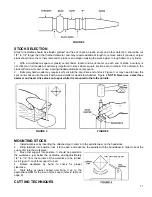
Insert the guard support rod in the guard mounting
bracket at the rear of the headstock. Position a
locking collar on each side of the mounting bracket so
that the lock pin lines up with the holes in the guard
pivot rod, one for guard position and one for load
position. The spring loaded lock pin will hold the
guard in each position.
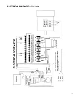
Power Connection
The lathe will operate on single phase or three phase
230 volt power supply. A three wire pigtail for use on
230 volt single phase power is attached to the inverter
and may be hard wired to the power source or
connected to a receptacle plug. Connect the 230 volt
supply to the black and white leads and ground the
green lead.
If three phase power is used, it will be necessary to
replace the pigtail wire with a 12/4 wire and connect
the three hot leads to the inverter at R, S and T as
shown in the wiring diagram. Always connect the
ground lead.
Before connecting to the power source make sure the
on/off switch is in the off position and turn the speed
dial counterclockwise. If the switch is in the on
position when the power is connected, the inverter will
trip out. If this happens, disconnect power, turn switch
off, wait 30 seconds and then reconnect power.
NOTICE: IF THERE IS A POWER OUTAGE WHILE
OPERATING THE LATHE, TURN THE SWITCH TO
THE OFF POSITION, DISCONNECT POWER
SOURCE, WAIT 30 SECONDS THEN RECONNECT
POWER SOURCE AND RESUME NORMAL
OPERATION.
Inverter Drive System
The model 4224 lathe utilizes the latest technology in
A.C. inverter drives to provide infinitely variable
spindle speeds. The inverter controls the speed of the
motor by varing the frequency of the voltage supplied
to the motor. The inverter provides an acceleration
ramp that eliminates the shock of normal across the
line starting. Also a braking feature eliminates long
coasting periods when the lathe is turned off.
The 3 HP motor is specially designed for use with
inverter drives, and is balanced to reduce noise and
minimize vibration.
The A.C. Inverter does not require any programming,
it is pre-programmed from the factory.
The buttons
on the face of the inverter should never be pushed
at any time.
Use only the controls on the front of the
headstock.
MAINTENANCE
Maintenance on the 4224 lathe should be performed
at periodic intervals to ensure that the machine is in
proper working order, that all fasteners are tight, and
the machine is in adjustment. The more use the
machine is subjected to, the more often it should be
inspected and maintained. Inspection and
maintenance should be performed at least twice a
year.
WARNING:
To prevent accidental starting or
electrical shock, disconnect machine from
power source before performing any
maintenance.
Periodic cleaning of the lathe is important to keep the
lathe in proper working order. The lathe bed should
be cleaned and oiled periodically so that headstock,
tailstock, and tool support will slide properly. With air
hose periodically blow out headstock to keep saw
dust and chips from collecting on belt and sheaves,
and blow off dust and chips that collect on inverter
(DO NOT DISASSEMBLE INVERTER TO CLEAN).
ADJUSTMENTS
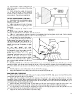
Belt Adjustment
The drive belt sheaves are initally aligned at the
factory, but if any service is performed that affects
their alignment it is very important that they be
realigned. To realign them, loosen the two set screws
on the spindle sheave and slide it in the proper
position. Use of a straight edge along the edge of both
sheaves will simplify the positioning. When properly
aligned, there should be no pulsing sounds or noise
coming from the belt.
!
Содержание 4224
Страница 17: ...17 ELECTRICAL SCHEMATIC 4224 Lathe ...
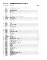
Страница 20: ...20 Stand Bed Assembly 4224 Lathe ...
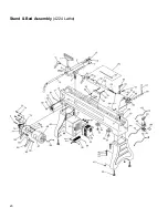
Страница 23: ...23 Headstock Assembly 4224 Lathe ...
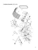
Страница 25: ...25 65 Bed Extension Assembly Optional 4224 Lathe ...
Страница 28: ...28 WMH Tool Group 2420 Vantage Drive Elgin Illinois 60123 Phone 800 274 6848 www wmhtoolgroup com ...


