background image


43


Содержание 3520B

Страница 1: ...oodturning Lathe Model 3520B shown with optional 18 inch bed extension and user made shelf WMH TOOL GROUP 2420 Vantage Drive Elgin Illinois 60124 Part No M 1352001 Ph 800 274 6848 Revision A1 8 06 www wmhtoolgroup com Copyright WMH Tool Group ...

Страница 2: ...or examination postage prepaid to a location designated by us For the name of the location nearest you please call 1 800 274 6848 You must provide proof of initial purchase date and an explanation of the complaint must accompany the merchandise If our inspection discloses a defect we will repair or replace the product or refund the purchase price at our option We will return the repaired product o...

Страница 3: ...Installing and Using 16 Speed Change 17 Sheave and Belt Alignment 18 Checking Spindle Play 18 Sheave Drive Belt Replacement 18 Operating Controls 19 Operation 20 Turning Tools 21 Spindle Turning 22 Cutting Techniques 23 Face Plate and Bowl Turning 25 Bowl Turning Techniques 26 Maintenance 27 Indexer Positions 28 Troubleshooting 29 Recommended Lathe Speeds per diameter of workpiece 30 Replacement P...

Страница 4: ...w often you do this type of work To reduce your exposure to these chemicals work in a well ventilated area and work with approved safety equipment such as face or dust masks that are specifically designed to filter out microscopic particles 10 Do not operate this machine while tired or under the influence of drugs alcohol or any medication 11 Do not expose this machine to rain or operate machine i...

Страница 5: ...occur if the machine tips over 29 Never leave the Lathe running unattended Turn the power off and do not leave the machine until it comes to a complete stop 30 Remove loose items and unnecessary work pieces from the area before starting the machine 31 Check the workpiece carefully for splits knots or other obstructions which may cause a safety risk while turning 32 Adjust the tool support to the p...

Страница 6: ...ed in 48 Maximum distance between spindle face and tailstock quill in 36 Swing over bed in 20 Maximum overall length in 73 Overall height to top of headstock in 49 1 2 Distance from floor to centerline of spindle in 45 Spindle speeds RPM high 125 3200 low 50 1200 Motor TEFC 2HP 220V 60Hz Lathe power requirements 220V 3Ph or 1Ph Spindle thread size in 1 1 4 x 8 TPI Headstock spindle taper 2 Morse T...

Страница 7: ...nual thoroughly for assembly maintenance and safety instructions Contents of the Shipping Container 1 Lathe Bed with Headstock Tailstock Tool Support Base A 2 Leg Assemblies B 1 Guard C 1 Tool Support 14 D 1 Face Plate 3 E 1 Live Center F 1 Spur Center 1 G 1 Index Pin H 1 Live Center Pin J 1 Knockout Rod K 1 Face Plate Wrench L 1 Tool Caddy M 4 Levelers N 12 Socket Hd Cap Screws 3 8 x 1 1 4 O 12 L...

Страница 8: ...have a hoist or forklift 4 If a forklift or hoist is not available the use of one or more assistants is mandatory First decrease the weight on the Lathe by removing the headstock tailstock and tool support base Refer to Headstock and Tailstock Movement on page 13 for removal instructions The headstock is heavy use caution when removing it from the lathe bed 5 Lift the Lathe bed and set it upside d...

Страница 9: ... Caddy The tool caddy shown in Figure 3 can be mounted to the left end or right end of the Lathe The left end near the headstock area is generally preferred for convenience Use two socket head cap screws and two lock washers with an 8mm hex wrench to secure the tool caddy to the threaded holes in the Lathe The tool caddy has holes for placing the knockout rod spur center live center live center pi...

Страница 10: ...tension into the threaded holes on the Lathe See Figure 7 3 Shift the bed extension upward so that it is slightly higher than the Lathe bed Tighten the screws with an 8mm wrench just enough to hold the bed extension to the Lathe bed IMPORTANT The surface of the bed extension must be level with the surface of the Lathe bed to allow smooth movement of the tailstock across the seam 4 Use a dead blow ...

Страница 11: ...lf has been established beneath the Lathe Shelf Style 1 Figure 10 Lay two 2x6 boards flat upon the inner ledges Boards of 48 length are suitable although 48 1 2 is optimal Shelf Style 2 Figure 11 Lay two 2x4 s or 2x6 s on edge into the outer ledges Boards of 48 length are suitable 48 1 2 optimal Cut two pieces from a plywood board and screw them to the top edges of the 2x4 s One 48 plywood piece w...

Страница 12: ...h the holes in the rear 2x6 as shown in Figure 12 7 A strip of wood can be screwed to the rear 2x6 to cover the dowel holes and prevent the dowels from working out Grounding Instructions Electrical connections must be made by a qualified electrician in compliance with all relevant codes This machine must be properly grounded to help prevent electrical shock and possible fatal injury This machine m...

Страница 13: ...ail wire attached to the inverter with a 12 4 wire and connect the three hot leads to the inverter at R S T as shown in the wiring diagram on page 40 Always connect the ground lead Extension cords If an extension cord is necessary make sure the cord rating is suitable for the amperage listed on the machine s motor plate An undersized cord will cause a drop in line voltage resulting in loss of powe...

Страница 14: ...e 15 3 Mount tailstock on bed and insert the stop bolt Tool Support A 14 tool support is provided with your Lathe It is designed to allow adjustment for height position on the bed and angle to the work Loosen the locking handle on the tool support base C Figure 16 to slide the support base forward or back and to angle it to the bed Tighten the locking handle firmly before operating the Lathe Loose...

Страница 15: ...piece for evenly spaced features 1 To use the indexer thread the index pin Figure 18 into one of the four holes until the index pin engages the spindle and prevents it from turning This will be your first indexing position 2 Unscrew and remove the index pin and look down the hole carefully counting the number of holes as you rotate the spindle using the handwheel Continue to rotate the spindle unt...

Страница 16: ...and tight When the Lathe is turned on forward rotation the rotational force will snug the face plate even further onto the threads If at any time you will be reversing spindle rotation make sure the two set screws in the face plate are tight One of these is shown in Figure 22 Failure to do this may cause the face plate to loosen from the headstock spindle 5 To remove the face plate loosen the two ...

Страница 17: ...uld be mounted last after all adjustment of the tailstock and ram has been accomplished with the spindle blank Likewise when turning operation is complete remove the reference spindle first Speed Change 1 Disconnect Lathe from power source 2 To change speed ranges pull open the access door on the headstock 3 Loosen the pivot lock handle A Figure 25 and lift up the tension handle B Figure 25 to rai...

Страница 18: ...tabbed lock washer C Figure 26 that interfere with the insets B Figure 26 on the spanner nut 2 Place the end of a flat head screwdriver down against one of the insets of the bearing lock nut B Figure 26 3 Tap the handle of the screwdriver with a mallet so that it turns the spanner nut A Figure 26 tighter in a clockwise direction Rotate the spanner nut only about 1 16 at a time Do not overtighten t...

Страница 19: ...wo set screws C Figure 25 and slide the sheave off the spindle 8 Install the new spindle sheave loosely securing the two set screws Make sure the sheave is oriented properly 9 Slide the spindle back into place install tabbed lock washer C Figure 26 and bearing lock nut B Figure 26 Check for any spindle play at this point See Checking Spindle Play section 10 Re install the handwheel and tighten the...

Страница 20: ...orsepower motor is specially designed for use with inverter drives and is balanced to reduce noise and minimize vibration The A C Inverter does not require any programming it is pre programmed from the factory The buttons on the face of the inverter should never be pushed at any time Use only the controls on the front of the headstock If you suspect there is a problem with the inverter or the inve...

Страница 21: ...dle Gouges 1 4 3 8 1 2 used to turn beads coves and other details Deep Fluted Bowl Gouge 1 4 3 8 and 1 2 used for turning bowls plates Square Scraper Bedan 3 8 or 1 2 used to create square shoulders Large Round Nose Domed Scraper 1 1 2 used to reduce ridges on interior of bowls round edges of bowls etc Parting Tool 1 8 used for scraping making a cut off or to set diameters for sizing For safety an...

Страница 22: ...can be removed later Larger stock should have the corners removed to produce an octagon making the piece easier to rough down to a cylinder 1 With a combination square or plastic center finder for round stock locate and mark center on each end of the workpiece Accuracy is not critical on full rounds but extremely important on stock where square sections are to remain Put a dimple in the stock with...

Страница 23: ...rkpiece to be turned as in Figure 32 Tighten support base to Lathe bed 11 Rotate workpiece by hand to check for proper clearance 12 Start lathe at lowest speed and bring it up to the appropriate RPM for the size of workpiece used Consult digital readout on the headstock Cutting Techniques Roughing Out 1 Begin with a large roughing gouge Place the tool on the tool support with the heel of the tool ...

Страница 24: ... this will result in a burned or burnished V with fibers being rolled up at both sides 2 Lightly mark the center of the V with the tip of the skew 3 Move the point of the skew to the right half of the desired width of your cut 4 With the bevel parallel to the right side of the cut raise the handle and push the tool in to the desired depth as shown in Figure 35 Figure 35 5 Repeat from the left side...

Страница 25: ...uire cyanoacrylate type glue Faceplate or Chuck While faceplates are the simplest most reliable method of holding a block of wood for turning chucks can also be used As there are dozens of chucks to choose from the woodturner should first consider all the different types of turning that will be done and read reports or discuss with other turners who own chucks before making a decision A chuck is n...

Страница 26: ...Tighten the ram locking handle 4 Turn workpiece by hand to ensure proper clearance 5 Start lathe at lowest speed and bring it up to the maximum safe speed for the size of work to be turned see page 30 If the machine starts to vibrate lower the speed until vibration stops 6 Rough out the outside of the bowl with the 1 2 deep fluted bowl gouge holding the handle of the tool firmly against your hip F...

Страница 27: ...eliminate Use power sanding techniques to avoid concentric sanding marks around your finished piece Avoid rounding over the rim and foot with sandpaper try to keep details crisp Finish sanding with 220 grit 3 Remove sanding dust with tack rags or compressed air and with lathe turned off apply first coat of finish Let stand for several minutes wipe off excess Allow to dry before sanding again with ...

Страница 28: ...nserted into hole combination A 5 this will be followed by A 9 Succeeding flutes will be made with the index pin in the B position B 2 B 6 and so on No of Flutes 360 divided by Angle Letter Letter Letter Letter 1 360 00 A 1 2 180 00 A 1 7 3 120 00 A 1 5 9 4 90 00 A 1 4 7 10 5 72 00 6 60 00 A 1 3 5 7 9 11 8 45 00 A 1 4 7 10 D 2 5 8 11 9 40 00 A 1 5 9 B 2 6 10 C 4 8 12 10 36 00 12 30 00 A 1 to 12 15...

Страница 29: ...vibration Lathe on uneven surface Adjust levelers Potentiometer faulty Replace potentiometer Lathe runs at one speed only Electronic AC inverter is not programmed properly or is defective or there is loose wiring Contact WMH Technical Service to help identify problem 800 274 6846 Dull tools Keep tools sharp see page 21 Tool support set too low Reposition tool support height See page 23 Tool suppor...

Страница 30: ... to 12 255 540 830 12 to 14 220 460 710 14 to 16 190 400 620 16 to 20 175 325 500 20 to 24 175 260 400 Replacement Parts Replacement parts are listed on the following pages To order parts or reach our service department call 1 800 274 6848 between 7 30 a m and 6 00 p m CST Monday through Friday Having the Model Number and Serial Number of your machine available when you call will allow us to serve...

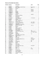
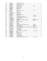
Страница 31: ...31 Headstock Assembly ...

Страница 32: ...on Lock Hex Nut 3 8 16 1 25 6095038 Bushing 1 26 6430045 Knob 2 27 3268219 Handle Headstock 1 28 3719189 Motor Sheave 1 29 2595036 Motor Assembly Plate 1 30 TS 0720091 Lock Washer 3 8 3 31 TS 0209061 Socket Head Cap Screw 3 8 16x1 1 4 3 32 3520B 232 Motor 2HP 220V 60Hz 1 33 JWL1642 166 Bracket 1 35 TS 0680042 Flat Washer 3 8 2 36 6350031 Motor Plate Locking Handle 1 37 JWL1642 130A Digital Readout...

Страница 33: ...77 TS 0560071 Hex Nut 10 24 2 78 TS 081C082 Phillips Pan Head Machine Screw 10 24x1 1 2 2 79 TS 069204 Washer 10 2 80 JML1642 169 Braking Resistor 1 81 6430047 Knob 1 82 3520B 282 Bracket 1 83 6295838 Phillips Round Head Machine Screw M3x20 2 84 TS 1490021 Hex Cap Screw M8x16 1 85 TS 0267021 Socket Set Screw 1 4 20x1 4 2 6294754 Knockout Rod Assembly includes index 86 thru 92 1 86 TS 0270031 Socke...

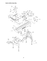
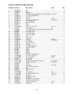
Страница 34: ...34 Stand and Bed Assembly ...

Страница 35: ... 24x3 4 1 22 6295910 Lock Handle 1 23 3728005 Quill Lock Sleeve 1 24 3520B 124 Tailstock 1 25 3520B 125 Tailstock Handwheel 1 26 3520B 126 Tailstock Handle 1 27 6430045 Knob 1 28 3268217 Handle 1 29 3092095 Clamp 1 30 6095038 Bushing 1 31 3708012 Tailstock Clamping Shaft 1 32 TS 0640091 Nylon Lock Hex Nut 3 8 16 1 33 TS 1490021 Hex Cap Screw M8x16 1 34 3520B 134 Cover Plate 1 35 6295717 Lock Knob ...

Страница 36: ... Washer 3 8 3 5 TS 0720091 Lock Washer 3 8 3 6 TS 0209081 Socket Head Cap Screw 3 8 16x1 3 4 3 6294726B 50 Bed Extension Assembly includes items 7 thru 15 7 3520B 101 50 Bed 1 8 3520B 102 Leg 1 9 TS 0570031 Hex Nut 3 8 16x1 2 10 6442000 Leveler 2 11 TS 0720091 Lock Washer 3 8 4 12 TS 0209061 Socket Head Cap Screw 3 8 x1 1 4 4 13 TS 0680042 Flat Washer 3 8 3 14 TS 0720091 Lock Washer 3 8 3 15 TS 02...

Страница 37: ...board Turning Stand Assembly items 1 thru 7 1 3042503 Turning Stand Base 1 2 6295897 Offset Tool Support Pin 1 00 diameter 1 3 6295898 Offset Tool Support Casting 1 00 hole 1 4 2695026 Screw Lock Assembly 3 5 3423055 Turning Stand Leg 1 6 6861700 Lock Washer 5 8 2 7 6769002 Socket Head Cap Screw 5 8 18 x 2 2 ...

Страница 38: ... Plate 1 1 4 8 7 6294733 Remote ON OFF Switch 6294730 12 Metal Spinning Tool Support Assembly includes items 8 9 8 12 Metal Spinning Tool Support 1 9 3585011 Tool Support Pin 5 8x 495x3 50 2 6294731 26 Tool Support Assembly includes items 10 11 12 10 26 Tool Support 1 11 6294795 Tool Support Post 2 12 6716219 Socket Head Cap Screw 3 8 16x6 1 4 2 13 6294740 Bowl Turning Tool Support R H 14 6294751 ...

Страница 39: ...t Hood 1 2 3520B 402 Upper Dust Hood 1 3 3520B 403 Hood Lock Knob Female 1 4 3520B 404 Lock Washer External Tooth M7 2 5 3520B 405 Hood Support Collar 1 6 3520B 406 Hood Lock Knob 3 7 3520B 407 Support Rod 1 8 3520B 408 Rod Holder 1 9 TS 1482021 Hex Cap Screw M6x12 4 10 TS 2361061 Lock Washer M6 4 11 3520B 411 Support Bracket 1 12 3520B 412 Lock Handle 2 ...

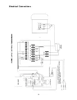
Страница 40: ...40 Electrical Connections ...

Страница 41: ... Run the remote switch s wiring harness through the opening in the back of the headstock and out through the front of the headstock 4 Connect the remote switch s wiring harness to the back of the Push Pull switch refer to the electrical schematic on page 40 5 Reinstall the control panel to the headstock From the back of the headstock lightly pull out any excess wire that may be inside the headstoc...

Страница 42: ...42 NOTES ...

Страница 43: ...43 ...

Страница 44: ...44 WMH Tool Group 2420 Vantage Drive Elgin Illinois 60124 Phone 800 274 6848 www wmhtoolgroup com ...

Отзывы: