Powered by Safety
®
25
Installation
01.4IB.51000C
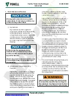
Table C Bolt Torque Values
Bolt
Dimensions
(inches)
Bolt
Head
Torque
Ft-Lbs
Kg-M
5/8
55-70
7.6-9.7
1/2
35-50
4.8-6.9
3/8
20-30
2.8-4.2
1/4
5-7
0.7-0.97
Note
: The bolt head drawings in Table C
are not to scale. Locate the Bolting
Torque label on the equipment for an
accurate drawing of bolt sizes.
k. m
AIn
B
uS
A
SSemBly
AnD
I
nSulAtIon
To insulate the main bus assembly, remove the
rear compartment covers. Then bolt the splice
plate and bus bars together, following the
assembly instructions in
!
CAUTION
The operating temperature of conductors
in the switchgear may reach 105
°
C. Any
insulating material used in this switchgear
must be suitable for this temperature.
To provide adequate bus joint insulation, use
any of the following methods:
• Wrapping bus joints, using tape or heat
shrink material
• Applying bus insulating boots
1) Main Bus Joint Insulation
Main bus joints are insulated with either a
custom fitted boot or with hand applied
insulating tape.
will describe the
procedure for hand applied insulating
tape wrapped joints. After installing
main bus conductors the joints must be
insulated as follows.
a. Tighten the bus bar splice plate bolts
properly. See
Table C Bolt Torque Values.
Once the joints are insulated, it will
not be possible to retorque the bolts
without removing the boot.
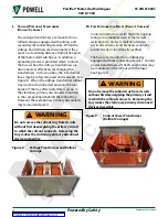
b. Place the boot over the joint (Figure 16).
Figure 16 Placing the Boot over the Joint
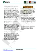
c. Align holes of each side of the boot.
d. Thread tie wraps through the holes and
pull tight, creating a seal (Figure 17, a).
e. An alternative method of assembly
uses push rivets (Figure 17, b). Push the
rivets completely through on both sides
of the boot. Verify the edges of the
boot seal.


