Poulan Pro 96192001900 Скачать руководство пользователя страница 17

17

1.  REMOVE GASOLINE FROM FUEL TANK - Drain gaso-

line from fuel tank into a suitable container, out doors, 

away from fire or flame. Wipe up any spilled gasoline.

2.  REMOVE DISCHARGE CHUTE - Loosen locknut 

se cur ing chute rotator head to mounting bracket only 

enough to allow chute rotator head to be raised and 

dis charge chute to be removed from snow thrower.

3.  REMOVE BELT COVER - See “TO REMOVE BELT 

COVER” in this section of this manual.

4.  REMOVE ENGINE PULLEY - Remove bolt, lock wash er 

and flat washer securing pulley to engine crankshaft.  

Remove outside (auger) pulley only from crank shaft.

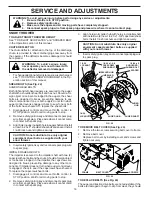
5.  SEPARATE SNOW THROWER - With your assistant 

standing in the operating position holding the handles, 

re move the two (2) bolts holding the auger housing and 

frame together.

WARNING: As the last bolt is removed, 

have your assistant carefully lower the 

han dles down to the ground.

6.  REMOVE HAIRPIN FROM CLUTCH ROD and remove 

clutch rod from swing plate.  Tip swing plate forward.

7.  REMOVE AUGER BELT from around pulley.
8.  RELIEVE TENSION ON TRACTION DRIVE BELT IDLER 

and remove traction drive belt from around pulleys.

HINT:

 Insert a 3/8" drive ratchet (in the “ON” position) into 

the square hole in idler arm and rotate ratchet clockwise 

to relieve tension.
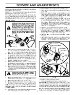
9.  With tension relieved on idler, install new traction drive 

belt around pulleys and inside belt keepers.

SERVICE AND ADJUSTMENTS

be replaced. It is recommended that the belt(s) be replaced 

by a qualified service center.

NOTE:

 It is recommended that both the auger and traction 

drive belt be replaced at the same time.
The V-belts on your snow thrower are of special con struc tion 

and should be replaced by original equipment man u fac tur er 

(OEM) belts avail able from your nearest dealer. Using other 

than OEM belts can cause personal injury or damage to 

the snow thrower.

WARNING: Belt replacement requires 

separation of the snow thrower. While 

separating the auger housing from the 

frame assembly, it is important that an 

assistant stand in the operating po si tion 

and hold the snow thrower han dles. Se-

rious personal injury and/or damage to 

the unit could occur if the snow thrower 

should fall during the belt chang ing 

process.

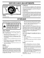
TO REMOVE WHEELS (See Fig. 25)

•  Remove the klik pin and remove wheel from axle.

IMPORTANT:

 When installing wheel, be sure to use the axle 

hole closest to the end of the shaft – 

do not

 use the hole 

in the wheel hub (if equipped).  Inner hole in axle and hole 

in wheel hub are not used for your model snow thrower.

NOTE:

 To seal punctures or prevent flat tires due to slow 

leaks, tire sealant may be purchased from your local parts 

dealer. Tire sealant also prevents tire dry rot and cor ro sion.
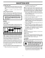
FRAME

ASSEMBLY

AUGER 

HOUS ING

HANDLES

10.  Install clutch rod in swing plate; secure with hairpin.
11.  Place auger belt around and inside the groove of auger 

pulley only.

12. While your assistant slowly raises handles to rejoin 

the auger hous ing and frame assembly, pull up on the 

auger belt and squeeze sides together above pulley 

so belt is fully seated in groove of pulley.

13. Bring snow thrower completely together and check 

carefully for proper routing of belts.  If auger belt has 

become dislodged from the pulley (by catching the idler 

arm bracket while bringing snow thrower together), 

separate the snow thrower and re peat step 12.  Belt 

must be fully seated in pulley groove when bring ing 

the snow thrower together.

14.  Install the two (2) hex bolts and tighten securely.
15.  INSTALL ENGINE PULLEY - Place belt in pulley groove 

and slide pulley on crankshaft.  Install flat washer, 

lockwasher and bolt and tighten securely (41-47 N-m 

torque).  Make sure belt is inside belt keeper.

16. INSTALL BELT COVER and two (2) screws. Tighten 

securely.

17.  INSTALL DISCHARGE CHUTE – See “INSTALL DIS-

 CHARGE CHUTE / CHUTE ROTATER HEAD” in the 

As sem bly / Pre-Operation section of this manual.

BELT KEEPER

IDLER ARM 

SQUARE 

HOLE

BOLTS

TRACTION DRIVE BELT

CLUTCHING 

IDLER ARM 

BRACKET

AUGER 

BELT

FLAT WASHER

AUGER PULLEY

AUGER

HOUSING

FRAME

ENGINE

PULLEY

LOCKWASHER

BOLT

FIG. 24

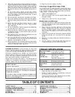
Содержание 96192001900

Страница 1: ...ER Always Wear Eye Protection During Operation IMPORTANT MANUAL Do Not Throw Away WARNING Read the Owner s Manual and follow all Warnings and Safety Instructions Failure to do so can result in serious injury 414741 Rev 3 09 19 07 TH Printed in U S A ...

Страница 2: ...own from the machine Operation 1 Do not put hands or feet near or under rotating parts Keep clear of the discharge opening at all times 2 Exercise extreme caution when operating on or cross ing gravel drives walks or roads Stay alert for hidden hazards or traffic 3 After striking a foreign object stop the engine motor remove the wire from the spark plug disconnect the cord on electric motors thoro...

Страница 3: ...gh transport speeds on slippery surfaces Look behind and use care when operating in reverse 13 Disengage power to the collector impeller when snow thrower is transported or not in use 14 Use only attachments and accessories approved by the manufacturer of the snow thrower such as wheel weights counterweights or cabs 15 Never operate the snow thrower without good visibility or light Always be sure ...

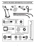
Страница 4: ...4 PARTS PACKED SEPARATELY IN CARTON ...

Страница 5: ...eaugerhousing to the pallet 4 Remove all packing materials except plastic tie holding speed control rod to lower handle 5 Remove the two 2 plastic ties securing the upper handle to the pallet 6 Remove snow thrower from carton and check carton thoroughly for additional loose parts HOW TO SET UP YOUR SNOW THROWER TOOL BOX See Fig 10 A toolbox is provided on your snow thrower The toolbox is located o...

Страница 6: ...EEVE LOOP OPENING UP FIG 5 INSTALL AUGER CONTROL ROD See Figs 5 and 6 The auger control rod has the short loop on the end of the spring as shown 1 Slide rubber sleeve up rod and hook end of spring into control arm with loop opening up as shown 2 With top end of rod positioned under right side of control panel push down on rod and insert end of rod into hole in auger control bracket Secure with ret...

Страница 7: ...purposes Correct and equal tire pressure is important for best snow throwing performance Reduce tire pressure to 14 17 PSI 19 24 5 N m INSTALL CHUTE DEFLECTOR REMOTE CONTROL See Figs 8 and 9 1 Install remote cable bracket to discharge chute with 5 16 18 carriage bolt and 5 16 18 locknut as shown Tighten securely 2 Install remote cable eyelet to chute deflector with 1 4 20 shoulder bolt nylon washe...

Страница 8: ...s Save this manual for future reference These symbols may appear on your snow thrower or in literature supplied with the product Learn and understand their meaning FORWARD PRIMER IGNITION KEY INSERT TO START AND RUN PULL OUT TO STOP READ AND FOLLOW ALL SAFETY INFORMATION AND INSTRUCTIONS BEFORE USE OF THIS PRODUCT KEEP THESE INSTRUCTIONS FOR FUTURE REFERENCE DANGER OR WARNING REVERSE SNOW DISCHARG...

Страница 9: ...d to cut through deep snowdrifts Primer pumps additional fuel from the carburetor to the cylinder for use when starting a cold engine Choke control used for starting a cold engine LH and RH turn triggers used to steer the snow thrower MEETS A N S I SAFETY REQUIREMENTS Our snow throwers conform to the standards of the American National Standards Institute RECOIL AUXILIARY STARTER HANDLE THROTTLE EN...

Страница 10: ...orward or reverse movement of the snow thrower AUGER Release the auger control lever to stop throwing snow ENGINE 1 Move throttle control to STOP position 2 Remove do not turn safety ignition key to prevent unauthorized use NOTE Never use choke to stop engine TO USE FUEL SHUT OFF VALVE See Fig 11 The fuel shut off valve is located beneath the fuel tank on the engine Always operate the snow thrower...

Страница 11: ...ting make certain all controls are disengaged and the auger impeller and all moving parts have stopped Disconnect the spark plug wire and keep the wire away from the spark plug to pre vent accidental starting Releasetheaugercontrolleverandshutofftheengine Removetheclean outtoolfromit smountingclip Grasp the tool firmly by the handle and push and twist the tool into the discharge chute to dislodge ...

Страница 12: ...nce to give a 1 8 clearance between the scraper bar and the ground Use a middle position if the surface to be cleared is uneven NOTE It is not recommended to operate the snow thrower overgravelorrockysurfaces Objectssuchasgravel rocks or other debris can easily be picked up and thrown by the impeller which can cause serious personal injury property damage or damage to the snow thrower If snow thro...

Страница 13: ...gine from starting If you do flood the engine wait a few minutes before attempting to start and DO NOT push the primer 5 Pull recoil starter handle quickly Do not allow starter rope to snap back OPERATION 6 Whentheenginestarts releasetherecoilstarterhandle and slowly move the choke control to the OFF posi tion Allow the engine to warm up for a few minutes Engine will not develop full power until i...

Страница 14: ...evel 2 Check for loose fasteners 3 Checkcontrolstobesuretheyarefunctioningproperly LUBRICATION Keep your snow thrower well lubricated See LUBRICATION CHART MAINTENANCE LUBRICATION CHART Engine oil Pivot points SNOW THROWER Always observe the safety rules when performing any maintenance TIRES Maintain proper air pressure in both tires 14 17 P S I 19 24 5 N m Keeptiresfreeofgasolineandoil whichcanha...

Страница 15: ...fill cap dipstick Be careful not to allow dirt to enter the engine 8 Refill engine with oil through oil dipstick tube Pour slowly Do not overfill For approximate capacity see PRODUCTSPECIFICATIONS sectionofthismanual 9 Use gauge on oil fill cap dipstick for checking level Be sure dipstick cap is tightened securely for accurate reading Keep oil at FULL line on dipstick 10 Wipe off any spilled oil M...

Страница 16: ...to see if one or both of the bolts have sheared To replace the shear bolts 1 Disengage all controls and move throttle control to STOP position Wait for all moving parts to stop 2 Remove safety ignition key and disconnect spark plug wire from spark plug Place wire where it cannot come in contact with spark plug 3 Alignholeinaugerhubwithholeinaugershaftandinstall anew1 4 20x2 shoulder shearboltandsp...

Страница 17: ...ousing from the frame assembly it is important that an assistantstandintheoperatingposition andholdthesnowthrowerhandles Se rious personal injury and or damage to theunitcouldoccurifthesnowthrower should fall during the belt changing process TO REMOVE WHEELS See Fig 25 Remove the klik pin and remove wheel from axle IMPORTANT Wheninstallingwheel besuretousetheaxle hole closest to the end of the sha...

Страница 18: ...gum deposits during storage Add stabilizer to gasoline in fuel tank or storage container Always follow the mix ratio found on stabilizer container Run engine at least 10 minutes after adding stabilizer to allow the stabilizer to reach the carburetor Do not drain the gas tank and carburetor if using fuel stabilizer ENGINE OIL Drain oil with engine warm and replace with clean en gine oil See ENGINE ...

Страница 19: ... FULL position 1 Move choke to OFF position runs roughly 2 Blockage in fuel line 2 Clean fuel line 3 Stale fuel 3 Drain tank and refill with fresh clean fuel 4 Water in fuel 4 Drain fuel tank and carburetor refill tank with fresh gasoline 5 Carburetor is in need of 5 Contact a qualified service centre adjustment or overhaul Excessive 1 Loose parts or damaged 1 Tighten all fasteners Replace damaged...

Страница 20: ...UGER HOUSING IMPELLER ASSEMBLY 6 6 5 9 9 12 7 7 8 6 11 57 10 10 13 4 14 16 15 36 37 50 47 42 42 44 27 27 43 43 46 38 45 41 40 39 34 32 49 19 48 51 33 35 30 31 28 19 55 28 19 55 22 18 26 25 20 58 25 26 29 20 24 18 10 24 54 52 53 53 21 54 58 21 52 17 17 56 1 3 2 ...

Страница 21: ...6192001900 AUGER HOUSING IMPELLER ASSEMBLY NOTE All component dimensions given in U S inches 1 inch 25 4 mm IMPORTANT Use only Original Equipment Manufacturer O E M replacement parts Failure to do so could be hazardous damage your snow thrower and void your warranty KEY PART NO NO DESCRIPTION 29 174762X479 Skid Plate LH 30 405973X479 Auger Assembly RH 31 405972X479 Auger Assembly LH 32 407768 O Ri...

Страница 22: ...22 REPAIR PARTS SNOW THROWER MODEL PP11530ES 96192001900 CONTROL PANEL DISCHARGE CHUTE 3 2 1 2 6 19 2 2 26 28 27 27 25 20 29 7 4 5 6 8 8 16 18 17 10 14 3 13 15 9 11 12 22 23 22 23 31 32 30 ...

Страница 23: ...18 15 404770X428 Chute Assembly 16 178633X428 Deflector Assembly 17 179145 Seal Deflector 18 128415 Rivet Blind 19 414281 Knob Speed Control Lever 20 72270506 Bolt Carriage 5 16 18 x 3 4 22 74041024 Screw 10 24 x 1 1 2 23 188303 Control Assembly Power Steering 25 155377 Nut Lock 5 16 18 26 198474 Lever Assembly Speed Control 27 169675 Retainer Hairpin 28 180445 Rod Upper Speed Control 29 187716 Ro...

Страница 24: ...W THROWER MODEL PP11530ES 96192001900 HANDLES 32 31 32 30 31 12 10 11 13 15 15 12 16 17 16 23 22 27 27 22 17 11 15 15 14 38 39 40 7 6 36 2 5 5 1 4 4 4 4 8 28 28 9 18 19 26 24 24 25 5 5 37 33 35 35 34 34 42 43 44 45 46 46 ...

Страница 25: ... Traction Drive 26 178669 Spring Auger Control 27 17000616 Screw Hex Head 3 8 16 x 1 28 412680 Bushing Pivot Lever 30 182906 Console Panel 31 175262 Screw Hex Head Tapping 10 24 x 1 1 4 32 184471 Screw Hex Head Tapping 10 24 x 1 2 33 196335X008 Latch Interlock 34 401369 Bolt Shoulder 35 68038 Nut Lock 1 4 20 36 178831 Spring Torsion Lever 37 193885 Spring Interlock 38 178666 Headlight Halogen Incl...

Страница 26: ...26 REPAIR PARTS SNOW THROWER MODEL PP11530ES 96192001900 DRIVE 4 4 4 4 4 2 2 43 11 1 1 22 5 5 5 2 2 20 41 21 17 13 3 6 14 19 18 18 15 24 36 35 34 37 31 9 12 23 26 29 25 4 4 33 28 32 27 44 ...

Страница 27: ...2187 Shaft Hex 13 402310 Pivot Rod Shifter 14 401732X479 Yoke Shifter 15 175344 Trunnion Bearing Assembly 17 178613 Hub Rubber Wheel 18 198176X479 Plate Rubber Wheel 19 74760514 Screw Hex Head 5 16 18 x 7 8 20 179831 Ring Rubber Wheel 21 73930500 Nut Lock 5 16 18 22 169675 Retainer Hairpin 23 180135 Spring Bias 24 402691 Sprocket Axle Shaft 25 402652 Pivot Rod Swing Plate 26 401820 Plate Drive 27 ...

Страница 28: ... PP11530ES 96192001900 CHASSIS ENGINE PULLEYS 6 19 17 10 21 22 23 2 3 4 6 42 8 9 12 13 15 27 26 25 24 18 7 20 14 5 40 46 44 49 50 51 52 35 34 33 38 37 39 43 11 32 32 36 36 44 45 41 30 29 31 31 11 11 1 5 5 5 16 56 47 53 10 21 28 57 6 58 ...

Страница 29: ... 18 x 1 1 2 19 175331 Bushing Idler Pivot 20 180523 Pulley Idler 2 3 4 21 74610516 Screw Hex Head 5 16 24 x 1 22 409475 Spacer Engine Pulley 23 180478 Pulley Engine Traction Drive 24 179157 Pulley Engine Impeller Drive 25 400026 Washer Flat 3 8 26 850263 Washer Lock 3 8 KEY PART NO NO DESCRIPTION 27 851084 Screw Hex Head 3 8 24 x 1 3 8 28 155452 Guide Belt 29 192213 Belt Cover Assembly Includes To...

Страница 30: ...1530ES 96192001900 WHEELS DECALS 32 30 32 30 15 18 17 19 13 20 11 27 27 19 16 20 11 11 11 11 14 15 12 13 18 14 12 4 4 31 34 34 2 3 21 33 22 23 24 25 26 28 28 29 10 4 4 28 28 26 29 25 24 23 22 33 21 1 2 3 7 8 7 9 5 3 1 4 2 1 10 7 6 8 9 11 12 ...

Страница 31: ... Lobe Axle 27 189282 Key Square 1 4 x 875 28 174697 Washer Thrust 1 29 179830 Bearing Axle 30 193885 Spring Return Steering Latch 31 196753X421 Wheel Assembly 16 Power Steering RH 32 700279 Clip Retainer 33 12000045 Ring Retaining 34 146315 Screw Hex Head Tapping 5 16 18 x 5 8 KEY PART NO NO DESCRIPTION 1 181037 Decal Danger 2 187867 Decal Poulan Pro 11 HP 30 3 181035 Decal Danger Deflector 4 1810...

Страница 32: ...is Warranty does not apply to any product which has been sub jected to alteration misuse abuse improper assembly or installation delivery damage or to normal wear of the product 5 Exclusions Excluded from this Warranty are belts shear pins normal wear normal adjustments standard hard ware and normal maintenance 6 In the event you have a claim under this Warranty you must return the product to an a...

Отзывы: