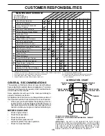
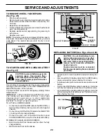
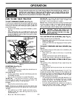
Poulan Pro 176085 Скачать руководство пользователя страница 12

12

OPERATION

TO OPERATE ON HILLS

CAUTION:  Do not drive up or down hills
with slopes greater than 15° and do not
drive across any slope.

Choose the slowest speed  before starting up or down
hills.

Avoid stopping or changing speed on hills.

If slowing is necessary, move throttle control lever to
slower position.

If stopping is absolutely necessary, push clutch/brake
pedal quickly to brake position and engage parking
brake.

Move motion control lever to neutral (N) position.

IMPORTANT:

THE  MOTION CONTROL LEVER DOES

NOT RETURN TO NEUTRAL (N) POSITION WHEN THE
CLUTCH/BRAKE PEDAL IS DEPRESSED.

To restart movement, slowly release parking brake and
clutch/brake pedal.

Slowly move motion control lever to slowest setting.

Make all turns slowly.
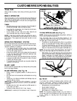
ATTACHMENT
CLUTCH LEVER
"DISENGAGED"
POSITION

ATTACHMENT
LIFT LEVER
HIGH POSI-
TION

"ENGAGED" POSITION

LOW
POSITION

FIG. 8

TOWING CARTS AND OTHER ATTACHMENTS

Tow only the attachments that are recommended by and
comply with specifications of the manufacturer of your
tractor. Use common sense when towing. Too heavy of a
load, while on a slope, is dangerous. Tires can lose traction
with the ground and cause you to lose control of your tractor.

FIG. 6

TO TRANSPORT (See Figs. 4 and 8)

When pushing or towing your tractor, be sure to disengage
transmission by placing freewheel control in freewheeling
position.  Free wheel control is located at the rear drawbar of
tractor.

Raise attachment lift to highest position with attach-
ment lift control.

Pull freewheel control out and down into the slot and
release so it is held in the disengaged position.

Do not  push or tow tractor at more than two (2) MPH.

To reengage transmission, reverse above procedure.

NOTE:  To protect hood from damage when transporting
your tractor on a truck or a trailer, be sure hood is closed and
secured to tractor.  Use an appropriate means of tying hood
to tractor (rope, cord, etc.).
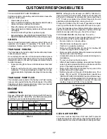
DEFLECTOR
SHIELD

TO OPERATE MOWER (See Fig. 7)

Your tractor  is equipped with an operator presence sensing
switch.  Any attempt by the operator to leave the seat with
the engine running and the attachment clutch engaged will
shut off the engine.

Select desired height of cut.

Start mower blades by engaging attachment clutch
control.

TO STOP MOWER BLADES - disengage attachment
clutch control.

CAUTION:  Do not operate the mower
without either the entire grass catcher,
on mowers so equipped, or the deflector
shield in place.

FIG. 7

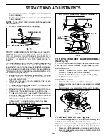
TO ADJUST GAUGE WHEELS (See Fig. 6)

Gauge wheels  are properly adjusted when they are slightly
off the ground when mower is at the desired cutting height in
operating position. Gauge wheels then keep the deck in
proper position to help prevent scalping in most terrain
conditions.

Adjust gauge wheels with tractor on a flat level surface.

Adjust mower to desired cutting height (See “TO AD-
JUST MOWER CUTTING HEIGHT” in the Operation
section of this manual).

With mower in desired height of cut position, gauge
wheels should be assembled so they are slightly off the
ground. Install gauge wheel in appropriate hole with
shoulder bolt, 17/32 washer, 3/8 washer, and 3/8-16
locknut and tighten securely.

Repeat for opposite side installing gauge wheel in same
adjustment hole.

GAUGE WHEEL

GAUGE
WHEEL
MOUNT-
ING
BRACKET

3/8-16
LOCKNUT

3/8 WASHER

SHOULDER
BOLT

17/32 WASHER

Содержание 176085

Страница 1: ...UAL MODEL NO PO165H42A 16 5 HP 42 Inch LawnTractor For Parts and Service contact our authorized distributor call 1 800 849 1297 For Technical Assistance call 1 800 829 5886 176085 Rev 1 2 23 01 RD PRINTED IN U S A ...

Страница 2: ... the slope Safe Operation Practices for Ride On Mowers IMPORTANT THIS CUTTING MACHINE IS CAPABLE OF AMPUTATING HANDS AND FEET AND THROWING OBJECTS FAILURE TO OBSERVE THE FOLLOWING SAFETY INSTRUCTIONS COULD RESULT IN SERIOUS INJURY OR DEATH SAFETY RULES DONOT Do not turn on slopes unless necessary and then turn slowly and gradually downhill if possible Do not mow near drop offs ditches or embankmen...

Страница 3: ...actices for Ride On Mowers SAFETY RULES SAFETY RULES 2 3 PRODUCT SPECIFICATIONS 4 CUSTOMER RESPONSIBILITIES 4 15 18 ASSEMBLY 6 8 OPERATION 9 14 MAINTENANCE SCHEDULE 15 SERVICE AND ADJUSTMENTS 19 23 STORAGE 24 TROUBLESHOOTING 25 26 REPAIR PARTS TRACTOR 28 43 TABLE OF CONTENTS Look for this symbol to point out im portant safety precautions It means CAUTION BECOMEALERT YOUR SAFETY IS INVOLVED CAUTION...

Страница 4: ...icians and the proper tools to service or repair this tractor Please read and retain this manual The instructions will enable you to assemble and maintain your tractor properly Always observe the SAFETY RULES CUSTOMER RESPONSIBILITIES Read and observe the safety rules Followaregularscheduleinmaintaining caringforand using your tractor Follow the instructions under Customer Responsibili ties and St...

Страница 5: ...asher 1 Locknut 5 16 18 1 Hex Bolt 5 16 18 x 1 1 4 1 Hex Bolt 3 8 16 x 1 1 Lockwasher 3 8 Steering Boot Steering Extension Shaft Steering Wheel Adapter 1 Bolt 1 Washer 17 32 x 1 3 16 x 12 Gauge Seat 2 Keys Slope Sheet Key 1 Lock Washer 1 2 1 Oil Drain Tube For Future Use ...

Страница 6: ...6 hex bolt and locknut Tighten securely Place tabs of steering boot over tab slots in dash and push down to secure INSTALL STEERING WHEEL Position front wheels of the tractor so they are pointing straightforward Removesteeringwheeladapterfromsteeringwheeland slide adapter onto steering shaft extension Positionsteeringwheelsocrossbarsarehorizontal left to right and slide inside boot and onto adapte...

Страница 7: ...gine Afterenginehasstarted movethrottle control to idle position Releaseparkingbrake Slowlymovethemotioncontrolleverforwardandslowly drive tractor off skid Applybraketostoptractor setparkingbrakeandplace motion control lever in neutral position Turn ignition key to OFF position Continue with the instructions that follow FIG 3 ADJUSTMENT BOLT LOCK WASHER NOTE You may now roll or drive your tractor ...

Страница 8: ...th fresh clean regular unleaded gasoline 3 Become familiar with all controls their location and function Operate them before you start the engine 3 Be sure brake system is in safe operating condition 3 Itisimportanttopurgethetransmissionbeforeoperating your tractor for the first time Follow proper starting and transmission purging instructions See TO START ENGINE and PURGETRANSMISSION intheOpera t...

Страница 9: ...ARD FAST SLOW ENGINE ON ENGINE OFF OIL PRESSURE LIGHTS ON FUEL CHOKE MOWER HEIGHT PARKING BRAKE LOCKED UNLOCKED REVERSE NEUTRAL HIGH LOW ATTACHMENT CLUTCH ENGAGED MOWER LIFT DANGER KEEP HANDS AND FEET AWAY FREE WHEEL Automatic Models only OVER TEMP LIGHT PARKING BRAKE IGNITION ATTACHMENT CLUTCH DISENGAGED P KEEP AREA CLEAR SLOPE HAZARDS 15 15 15 SEE SAFETY RULES SECTION ...

Страница 10: ...UTCH BRAKE PEDAL Used for declutching and brak ing the tractor and starting the engine PARKINGBRAKE Locksclutch brakepedalintothebrake position FREEWHEEL CONTROL Disengages transmission for pushing or slowly towing the tractor with the engine off MOTION CONTROL LEVER Selects the speed and direction of tractor ATTACHMENT LIFT LEVER Used to raise and lower the mower deck or other attachments mounted...

Страница 11: ...throttle control to slow position NOTE Failure to move throttle control to slow position and allowingenginetoidlebeforestoppingmaycauseengineto backfire Turn ignition key to OFF position and remove key Always remove key when leaving tractor to prevent unauthorizeduse Never use choke to stop engine PARKING BRAKE ENGAGED POSITION MOTION CONTROL LEVER THROTTLE CHOKE CONTROL IGNITION KEY DISENGAGED PO...

Страница 12: ...ase so it is held in the disengaged position Do not push or tow tractor at more than two 2 MPH To reengage transmission reverse above procedure NOTE To protect hood from damage when transporting yourtractoronatruckoratrailer besurehoodisclosedand secured to tractor Use an appropriate means of tying hood to tractor rope cord etc DEFLECTOR SHIELD TO OPERATE MOWER See Fig 7 Yourtractor isequippedwith...

Страница 13: ...k on dipstick is reached Do not overfill For cold weather operation you should change oil for easier starting See OIL VISCOSITY CHART in the Customer Responsibilities section of this manual To change engine oil see the Customer Responsibili ties section in this manual TO START ENGINE See Fig 4 Whenstartingtheengineforthefirsttimeoriftheenginehas run out of fuel it will take extra cranking time to ...

Страница 14: ...attachments select a ground speed thatwillsuittheterrainandgivebestperformanceofthe attachment being used OPERATION Sitting in the tractor seat start engine After the engine is running move throttle control to slow position With motion control lever in neutral N position slowly disengageclutch brakepedal Move motion control lever to full forward position and hold for five 5 seconds Move lever to f...

Страница 15: ...7 Tighten front axle pivot bolt to 35 ft lbs maximum Do not overtighten 1 12 3 2 5 5 6 7 GENERAL RECOMMENDATIONS The warranty on this tractor does not cover items that have beensubjectedtooperatorabuseornegligence Toreceive full value from the warranty operator must maintain tractor as instructed in this manual Some adjustments will need to be made periodically to properly maintain your tractor Al...

Страница 16: ...inte nance BRAKE OPERATION If tractor requires more than six 6 feet stopping distance at high speed in highest gear then brake must be adjusted See TOADJUSTBRAKE intheServiceandAdjustments section of this manual TIRES Maintainproperairpressureinalltires See PRODUCT SPECIFICATIONS section of this manual Keep tires free of gasoline oil or insect control chemi cals which can harm rubber Avoid stumps ...

Страница 17: ... 40 F C 32 10 10 60 5W 30 SAE 30 NOTE Although multi viscosity oils 5W30 10W30 etc improve starting in cold weather these multi viscosity oils will result in increased oil consumption when used above 32 F Check your engine oil level more frequently to avoid possible engine damage from running low on oil Change the oil after every 25 hours of operation or at least onceayearifthetractorisnotusedfor2...

Страница 18: ...ce paper cartridge every 100 hours of operation or every season whichever occurs first Service air cleaner more often under dusty conditions Remove knob s and cover TO SERVICE PRE CLEANER Slide foam pre cleaner off cartridge Wash it in liquid detergent and water Squeeze it dry in a clean cloth Saturateitinengineoil Wrapitinclean absorbentcloth and squeeze to remove excess oil If very dirty or dama...

Страница 19: ...ACTOR TO REMOVE MOWER See Fig 17 Mower will be easier to remove from the right side of tractor Place attachment clutch in DISENGAGED position Move attachment lift lever forward to lower mower to its lowest position Roll belt off engine pulley Remove small retainer spring and lift clutch spring off pulley bolt Remove large retainer spring slide collar off and push housing guide out of bracket Disco...

Страница 20: ...osen lift link adjustment nut on that side NOTE Threefullturnsofadjustmentnutwillchangemower height about 1 8 Recheck measurements after adjusting FRONT TO BACK ADJUSTMENT See Figs 20 and 21 IMPORTANT DECK MUST BE LEVEL SIDE TO SIDE IF THE FOLLOWING FRONT TO BACK ADJUSTMENT IS NECESSARY BE SURE TO ADJUST BOTH FRONT LINKS EQUALLY SO MOWER WILL STAY LEVEL SIDE TO SIDE Toobtainthebestcuttingresults t...

Страница 21: ... See PURGE TRANSMIS SION in the Operation section of this manual ADJUSTMENT BOLT FIG 25 NEUTRAL LOCK GATE MOTION CONTROL LEVER TO ADJUST STEERING WHEEL ALIGNMENT If steering wheel crossbars are not horizontal left to right whenwheelsarepositionedstraightforward removesteer ing wheel and reassemble per instructions in the Assembly section of this manual FRONT WHEEL TOE IN CAMBER Thefrontwheeltoe in...

Страница 22: ...rt square key Replace washers and snap retaining ring securely in axle groove Replace axle cover NOTE To seal tire punctures and prevent flat tires due to slow leaks tire sealant may be purchased from your local parts dealer Tire sealant also prevents tire dry rot and corrosion FIG 26 RETAINING RING WASHERS SQUARE KEY REAR WHEEL ONLY AXLE COVER TO START ENGINE WITH A WEAK BATTERY See Fig 27 CAUTIO...

Страница 23: ...houldnotbenecessary However minoradjustment may be required to compensate for differences in fuel temperature altitude or load If the carburetor does need adjustment see engine manual Highspeedstopisfactoryadjusted Donotadjust damage may result IMPORTANT NEVER TAMPER WITH THE ENGINE GOVERNOR WHICH IS FACTORY SET FOR PROPER ENGINE SPEED OVERSPEEDING THE ENGINE ABOVE THE FACTORY HIGH SPEED SETTING C...

Страница 24: ...NG IN ESSENTIAL FUEL SYSTEM PARTS SUCH AS CARBURETOR FUEL FILTER FUEL HOSE OR TANK DURING STORAGE ALSO EXPERIENCE INDICATES THAT ALCOHOL BLENDED FUELS CALLED GASOHOL OR USING ETHANOL OR METHANOL CAN ATTRACT MOISTURE WHICH LEADS TO SEPARATION AND FORMATION OF ACIDS DURING STORAGE ACIDIC GAS CAN DAMAGE THE FUEL SYSTEM OF AN ENGINE WHILE IN STORAGE Drain the fuel tank Start the engine and let it run ...

Страница 25: ...heck replace ignition switch 8 Faulty solenoid or starter 8 Check replace solenoid or starter 9 Faulty operator presence switch es 9 Contact an authorized service center department Engine clicks but will not 1 Weak or dead battery 1 Recharge or replace battery start 2 Corroded battery terminals 2 Clean battery terminals 3 Loose or damaged wiring 3 Check all wiring 4 Faulty solenoid or starter 4 Ch...

Страница 26: ...eplace sharpen blade Tighten blade bolt 7 Buildup of grass leaves and trash under mower 7 Clean underside of mower housing 8 Mower drive belt worn 8 Replace mower drive belt 9 Blades improperly installed 9 Reinstall blades sharp edge down 10 Improper blades used 10 Replace with blades listed in this manual 11 Clogged mower deck vent holes from buildup of 11 Clean around mandrels to open vent holes...

Страница 27: ...NOTE YOUR TRACTOR IS EQUIPPED WITH A SPECIAL ALTERNATOR SYSTEM THE LIGHTS ARE NOT CONNECTED TO THE BATTERY BUT HAVE THEIR OWN ELECTRICAL SOURCE BECAUSE OF THIS THE BRIGHTNESS OF THE LIGHTS WILL CHANGE WITH ENGINE SPEED AT IDLE THE LIGHTS WILL DIM AS THE ENGINE IS SPEEDED UP THE LIGHTS WILL BECOME THEIR BRIGHTEST WIRING INSULATED CLIPS NOTE IF WIRING INSULATED CLIPS WERE REMOVED FOR SERVICING OF UN...

Страница 28: ...28 REPAIR PARTS TRACTOR MODEL NUMBER PO165H42A ELECTRICAL 28 29 26 24 42 43 27 27 25 41 27 27 40 33 30 8 2 1 27 16 16 52 D C AM PE RE S 45 22 21 ...

Страница 29: ... 6 Ga 11 red 25 146147 Cable Battery 6 Ga w 16 wire red 26 175158 Fuse 20 AMP 27 73510400 Nut Keps Hex 1 4 20 unc 28 4207J Cable Ground 6 Ga 12 black 29 121305X Switch Plunger Nc Gray 30 175566 Switch Ign 33 140401 Key Ign 40 170217 HarnessIgn 41 71110408 Bolt Blk Fin Hex 1 4 20 X 1 2 42 131563 CoverTerminalRed 43 175141 Solenoid 45 121433X Ammeter 52 141940 ProtectionWireLoop KEY PART NO NO DESCR...

Страница 30: ...CTOR MODEL NUMBER PO165H42A CHASSIS AND ENCLOSURES 3 2 35 3 26 35 3 26 33 10 34 1 208 11 17 29 28 208 13 12 51 57 53 52 54 55 24 26 25 26 25 3 31 24 30 209 8 209 6 16 9 15 209 209 5 5 58 145 37 37 18 206 205 205 38 38 212 ...

Страница 31: ... 28 140434 Grill Lens Asm 29 140273X599 Lens Grille Private label 30 169467X428 Fender Asm 31 136619 BracketFender 33 145244X428 Footrest 34 145243X428 Footrest 35 72110606 Bolt RdHd Sht Sqnk 3 8 16 x 3 4 37 17490508 Screw Thdrol 5 16 18 x 1 2 Tyt 38 169834 Bracket Asm Pivot Mower Rear 51 73800400 Nut Lock Hex W Ins 1 4 20 52 19091416 Washer 9 32 x 7 8 x 16 Ga 53 144697 Bracket Grille LH 54 161464...

Страница 32: ...69 56 64 65 212 63 116 70 57 66 27 51 48 151 202 49 47 50 120 150 156 166 165 82 168 163 14 164 21 8 10 83 159 161 198 158 162 171 169 29 28 32 30 52 32 53 35 55 36 62 35 36 22 34 61 16 1 77 77 30 61 52 96 26 25 19 24 26 26 27 26 15 37 84 16 199 16 61 71 200 73 16 61 95 197 103 205 76 78 75 74 ...

Страница 33: ...86 Pulley Engine 64 71170764 Bolt Hex 7 16 x 4 Gr 5 65 10040700 Washer 66 154778 Keeper Belt Engine Hydro 69 142432 Screw Hex Wsh Hi Lo 1 4 1 2 Unc 70 134683 Guide Belt Mower Drive RH 71 169183 Strap Torque Lh 72 19132012 Washer 13 32 x 1 1 4 x 12 Ga 73 169182 Strap Torque Rh 74 137057 Spacer Axle 75 121749X Washer 25 32 x 1 1 4 x 16 Ga 76 12000001 Ring E 77 123583X Key Square 78 121748X Washer 25...

Страница 34: ...UMBER PO165H42A STEERING ASSEMBLY 62 44 51 54 5 9 5 7 7 9 4 3 32 43 6 43 8 18 19 22 27 23 40 66 29 25 79 8 10 40 11 8 6 9 46 46 8 6 9 2 47 47 17 26 30 28 1 41 42 37 36 37 38 63 11 39 11 80 68 67 67 67 13 65 85 85 68 15 15 15 29 29 82 ...

Страница 35: ... 8 16x3 4 30 76020412 Pin 32 130465 Rod Tie Wire Form 19 75 Mech 36 155099 Bushing Strg 5 8 Id Dash 37 152927 Screw TT 10 32 x 5 x 3 8 Flange 38 140045X428 Insert Cap Strg 39 19133812 Washer 13 32 x 2 3 8 x 12Ga 40 7810H LocknutCenter 41 100711L Adaptor Wheel Strg 640 635id 42 145054X428 Boot Dash Steering 43 121749X Washer 25 32 X 1 1 4 X 16 Ga 44 153720 ExtensionSteeringNon Adjust 46 121232X Cap...

Страница 36: ...36 REPAIR PARTS TRACTOR MODEL NUMBER PO165H42A ENGINE 2 1 OPTIONAL EQUIPMENT Spark Arrester 29 44 46 32 31 33 37 33 40 62 13 4 72 78 81 3 16 78 23 45 14 38 ...

Страница 37: ...sher Lock Ext Tooth 3 8 23 169837 ShieldBrowning DebrisGuard 29 137180 ArrestorSpark 31 109202X Tank Fuel 1 25 Fr 32 140527 Cap Asm Fuel W sym Vented 33 123487X Clamp Hose Blk 37 137040 Line Fuel 20 38 148315 Plug Drain Oil Easy 40 124028X Bushing Snap Nyl Blk Fuel Line 44 17670412 ScrewHexwshThdrol1 4 20x3 4 45 17000612 Screw Hex Wsh Thdrol 3 8 16 46 19091416 Washer 9 32 X 7 8 X 16ga 62 10040500 ...

Страница 38: ...2 Washer 17 32 x 1 3 16 x 12 Ga 25 127018X Bolt Shoulder 5 16 18 x 62 26 10040800 Lockwasher 26 23 1 24 16 15 12 13 17 25 4 3 8 9 7 8 9 7 2 6 22 21 5 10 5 14 1 140116 Seat 2 140551 Bracket Pnt Pivot Seat blk 3 71110616 Bolt 4 19131610 Washer 13 32 x 1 x 10 Ga 5 145006 ClipPush InHinged 6 73800600 Nut 7 124181X Spring Seat Cprsn 2 250 Blk Zi 8 17000616 Screw 3 8 16 x 1 5 9 19131614 Washer 13 32 x 1...

Страница 39: ...ealant Tire 10 oz Tube NOTE All component dimensions given in U S inches 1 inch 25 4 mm KEY PART NO NO DESCRIPTION KEY PART NO NO DESCRIPTION 10 157140 DecalDangerEnglish 11 101892X Decal Clutch brake English 12 175784 DecalFender 14 160396 Decal V belt Schematic 42 16 145005 DecalBatteryDanger Poison 20 170945 Decal HP Engine 133671 Pad Footrest 138311 Decal Lift Handle 176085 ManualOwner sEnglis...

Страница 40: ...40 REPAIR PARTS TRACTOR MODEL NUMBER PO165H42A MOWER LIFT 15 20 16 1718 20 20 15 20 4 5 6 2 3 1 6 5 4 7 8 12 11 31 32 31 32 19 19 13 13 13 13 ...

Страница 41: ...3X GripHandle 8 124526X ButtonPlunger 11 139865 Link Lift Lh 12 139866 Link Lift Rh 13 4939M RetainerSpring 15 173288 Link Front 16 73350800 Nut Jam Hex 1 2 13 Unc 17 130171 Trunnion Blk Zinc 18 73800800 Nut Lock w Wsh 1 2 13 Unc 19 139868 Arm Suspension Rear 20 163552 RetainerSpring 31 169865 Bearing Pvt Lift 32 73540600 Nut Crownlock 3 8 24 KEY PART NO NO DESCRIPTION NOTE All component dimension...

Страница 42: ...32 33 146 148 145 150 45 144 147 147 142 149 142 49 50 51 54 52 53 55 56 34 1 46 44 21 22 24 25 26 27 2 28 29 23 21 21 21 18 18 20 2 48 59 19 4 3 5 6 21 40 143 36 40 37 40 159 152 151 153 154 157 158 67 153 156 155 114 117 119 116 115 111 118 121 113 120 113 117 116 118 119 114 115 112 121 120 ...

Страница 43: ...de 5 51 69180 Locknut 52 139888 Bolt Shoulder 5 16 18 UNC 53 131845 Arm Assembly Pad Brake 54 133943 Washer Hardened 55 155046 Arm Idler 56 165723 Spacer Retainer 59 141043 Guard TUV Idler 67 106932X Knob 68 144959 V Belt 42 Mower 111 155197 Bracket Gauge Wheel LH 112 155198 Bracket Gauge Wheel RH 113 17060514 ScrewTapping5 16 18Unc 114 73510500 Nut Keps 5 16 18 UNC 115 72110504 Bolt Carriage 5 16...

Страница 44: ...44 SERVICE NOTES ...

Страница 45: ...45 SERVICE NOTES ...

Страница 46: ...s limited to 90 days from the date of original purchase 5 This Warranty applies only to products which have been properly assembled adjusted operated and main tained in accordance with the instructions furnished This Warranty does not apply to any product which has been subjected to alteration misuse abuse improper assembly or installation delivery damage or to normal wear of the product 6 Exclusi...

Страница 47: ...IDE ONLY RIDE UP AND DOWN HILL NOT ACROSS HILL SUGGESTED GUIDE FOR SIGHTING SLOPES FOR SAFE OPERATION Operate your Tractor up and down the face of slopes not greater than 15 never across the face Make turns gradu ally to prevent tipping or loss of control Exercise extreme caution when changing direction on slopes ...

Страница 48: ......

Отзывы: