background image

- 14 -

1300_GB-ABBAUEN_3784

GB

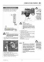
DISMOUNT AND PARKING

Attention!

• Always park 

implement stead-

fast!

• Use support stand 

- otherwise dan-

ger of tipping!

• Danger of injury 

from crushing and 

shearing sections 

in the area of the 

support stand!

 Note

  The safety lever (1) is a safety fixture. Its 

shape and function must not be altered.

  The lever is so constructed that it won’t 

spring out of the lock position when 
hydraulically raising the mower bar.

• 

Do not operate the hydraulic cylinder to 
slew across the mowing bar when the lever 
is in the bolt position

• 

Exchange damaged levers immediately for 
new ones.

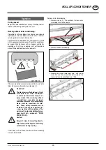
Detach machine from tractor

Depending on parking situation, mower can be detached 
in the transport position (H) or working position (R).
The following procedure applies to both situations:

Take note!

  Only leave tractor to detach mower when it 

is stationary and has been secured against 
rolling, and when mower has been lowered 
onto firm, even ground.

1.  Set the single-action control unit to floating position to 

lower the implement to the required parking position 
(H, R).

2.  Swivel safety lever (1) to (Pos. A)
3.  Extend or fold down support stands (2) and secure
4.  Lower implement onto support stands.
5.  Relieve the arrester hook by adjusting the hydraulic 

lower link arm (with dual-action control unit).

 Beware!

  Check safety lever (1)!

  It must be swivelled to (Pos. A)!

  Otherwise there is the danger that when 

uncoupling, the lower link of the mower’s 
mounting frame swivels up in jerks and 
jolts.

6.  Uncoupling the upper link
7.  Take control line from tractor cabin and place, rolled 

up, on mower’s hose storage.

8.  Untension and cap off the hydraulic hoses and place 

them on the hose rest of the mower

9.  Unplug tractor’s 7-pole lighting plug
10. Uncouple cardan shaft and lay on cardan shaft holder.
11. Separate the tractor’s lower link from the machine’s 

lower link pins

12. Carefully move the tractor away.

Pos. A

Pos. B

1

2

Be advised!

Use the lower link 

arm hydraulic sys-

tem to relieve the 

arrester hook and 

do not use force. 

Using force (e.g.  

hammer) may lead 

to injury

H

r

Содержание NOVACAT 352 CF

Страница 1: ...Operator s manual GB INSTRUCTIONS FOR PRODUCT DELIVERY Page 3 Translation of the original Operating Manual Nr Disc mower 99 3784 GB 80R 1 NOVACAT 352 ED RC CF Type PSM 3784 0291 ...

Страница 2: ...apply the highest quality standards to our products which are constantly monitored by our in house quality management and our management board Because the safety perfect function highest quality and absolute reliability of our machines in operation are the core competencies for which we stand There may be deviations between these instructions and the product as we are constantly developing our pro...

Страница 3: ...or carried out to three point linkage Trial run carried out and no defects found Functions explained during trial run Pivoting in transporting and operating position explained Information given re optional extras Absolute need to read the operating manual indicated Please check X According to the product liability please check the above mentioned items INSTRUCTIONS FOR PRODUCT DELIVERY GB In order...

Страница 4: ...LLER CONDITIONER Safety advice 23 Operation mode 23 Possible settings 24 Operation 25 Maintenance 26 CROSS FLOW Overview 29 Safety advice 29 Mode of operation 30 CF unit operation 30 Tailgate 30 Scraper 31 Swath width option 31 Maintenance 32 Mowing without conditioner 34 Optional equipment 34 Swath width when mowing without conditioner 35 Conveying cones optional 35 Reverse the three screws in th...

Страница 5: ...ing the EU Declaration of Conformity the manufacturer declares that the machine being brought into service complies with all relevant safety and health requirements Meaning of warning signs Danger flying objects keep safe distance from the machine as long as the engine is running Wait until all machine components have stopped completely before touching them Stay clear of mower knife area as long a...

Страница 6: ...SICHT_3784 GB SPECIFICATION Overview Designations 1 Headstock 2 Hydraulic relief 3 Cutter bar 4 Conditioner 5 Foldable side protection Variations Description Description NOVACAT 352 ED RC Working width 3 46 m 1 5 4 3 2 ...

Страница 7: ...ar three point linkage The tractor s lifting unit three point linkage must be designed for the load that occurs See technical data The lifting struts are to be set at the same length 4 using the relevant adjusting equipment See the tractor manufacturer s operating manual Selecttherearpositioniftheliftingrodscanbeadjusted in various positions on the lower link This relieves the pressure on the trac...

Страница 8: ...raulic lower link compensator or swivel cylinder with active control line if cross valve at bottom Hydraulic relief X Operating pressure Be advised Checkthecompatibilityofthehydraulicoilsbeforeconnecting the implement to the hydraulic system of your tractor Do not mix mineral oils with bio oils Operatingpressureminimum 170 bar Operatingpressuremaximum 200 bar Necessary power connections Design Con...

Страница 9: ... the rear tractor tyres Beware Ensure fixing screw is inserted in required hole see figure below on the bolt Otherwise mower may come loose from coupling and drop to the ground causing property damage Safety hints see Supple ment A1 7 8a 8h Caution This implement is designed for operation with a tractor not for self drive work machines 3 drilled holes Fixing screw Connect upper link and secure Be ...

Страница 10: ... value on manometer for machine without conditioner 110 bar for machine with conditioner 145 150 bar Note Note that the degree of dirt accumulation affects the ground pressure of the machine Set the right lower link 1 Put the mower unit in floating position using the single acting servo 2 Movetheliftinggearintheappropriatedirectionuntil the indicator arrow points 1 on the relief cylinder point dir...

Страница 11: ...arance for the NOVACAT 302 is approx 700 mm to the right lower link pin and 650 mm for the NOVACAT 262 Set power take off r p m Set appropriate power take off r p m on tractor Note An transfer located near the gearing advises which power take off r p m the disk mower is designed for Check rotation direction The power take off rotation direction is suitable when looking from the front the outer cut...

Страница 12: ...tanding in the mower s swivel range 1 Raise the mower into field transport position using the single action control unit Change from field transport position to transport position Procedure 1 Turn drive off and wait for mower discs to come to a standstill Be alert Ensure that no one is standing in the mower s swivel range 2 Pull control line 3 Atthesametimeswivelthemowerintotransportposition using...

Страница 13: ...tanding in the mower s swivel range 1 Pull control line 2 At the same time swivel the mower into field transport position until the swivel cylinder is completely extended using the dual action control unit Note If the dual action control unit is activated withouthavingpulledthecontrolline then thehorizontalpositionofthehitchchanges 3 Set the single action control unit to floating position and thus...

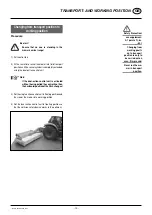
Страница 14: ...ground 1 Set the single action control unit to floating position to lower the implement to the required parking position H R 2 Swivel safety lever 1 to Pos A 3 Extend or fold down support stands 2 and secure 4 Lower implement onto support stands 5 Relieve the arrester hook by adjusting the hydraulic lower link arm with dual action control unit Beware Check safety lever 1 It must be swivelled to Po...

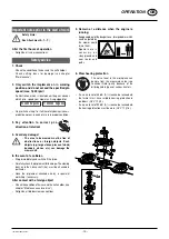
Страница 15: ...the event of a collision Stop immediately and switch off the drive Carefullychecktheimplementfordamage Themowing discs and their drive shaft 4a must be checked in particular Have the implement checked also by a specialist workshop if necessary After contact with a foreign object Check the condition of knives and the knife holder see chapter Maintenance and service Retighten all blade screw connect...

Страница 16: ...ion Headstock Set the headstock horizontal Changes can be performed with the hydraulic lower link compensator 1 Set 3 way cock at headstock downwards to select the function Hydraulic lower link 2 Activate the dual action control unit at the tractor until the attachment frame is horizontal Lift out cylinder The lift out cylinder control unit is to be switched to floatingpositionduringusetoachieveco...

Страница 17: ...lopes Danger of tipping occurs when the mower unit is facing downhill and in a raised position when travelling in a left hand curve with the mower unit raised Safety information Reduce speed correspondingly in curves left Drive so that the raised mower unit is positioned up the slope It is better to travel in reverse on a slope than to carry out a risky turning manoeuvre TD15 95 3 G Note Raise the...

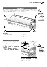
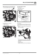
Страница 18: ...arly the safety informa tion prior to initial operation Designations 1 Adjustable swath board 3 Drive unit 2 Tine rotor 4 Intensity adjustment unit 5 V belt tensioner 1 4 2 3 5 Possible settings Foroptimaladaptationtothesurroundingconditions make the following adjustments to the tine conditioner Setting the conditioning effect The distance between the adjusting strip and the rotor is set using lev...

Страница 19: ...must be flush with the shim then the belt tension is correct 1 Rotor tines position Pos Z1 Rotortinespositionfornormaloperatingconditions Pos Z2 For difficult operating conditions e g if the fodder winds around the rotor Turn the rotor tines 180 pos Z2 This tine position solves theprobleminmostcases However theconditioningeffect is thereby somewhat reduced Rotor tine maintenance 1 Replacing tine f...

Страница 20: ...below are to be regarded as basic settings The optimum swath width can be determined perhaps only in practical use due to the various types of fodder Wide spreading Swivel the swath plates S completely out Set the position of the guide plates see illustration B 278 09 52 B S S Swathes Swivel the swath plates S in Set the position of the guide plates see illustration L 278 09 53 L S S ...

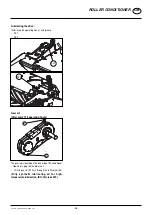
Страница 21: ...uncoupled 2 Release the locking screw 3 3 3 Swivel the rear side guard up 4 Remove the V belt cover 2 screws 5 Pull the cardan shaft off 6 Insert the V belt tension lever 4 into the guide 5 provided for this 4 5 7 Relieve the V belt by pressing the belt tension lever down 8 Disengage the V belt 9 Re fit the cardan shaft 10 Insert the conditioner chassis left as far as possible into the opening int...

Страница 22: ...ked 15 Always park conditioner CR stably CR Fitting the conditioner CR the swath former SF or the rear protection component is carried out similarly to removal but in the reverse order Important When mowing without condi tioner additional safety elements and both swath formers must be attached to the cutter bar See the spare parts list for the parts If additional protec tion elements are fitted re...

Страница 23: ...r lucerne and clover types Two power driven interlocking rollers crush the fodder In so doing the plant s natural wax coating is damaged and the drying time is accelerated 224 16 11 A B D E F G H C Designations A Adjusting screw for conditioning intensity E Main drive unit B Swath width adjusting lever F Rubber rollers C Swath plate G Auxiliary drive unit top roller D Main drive adjusting screw H ...

Страница 24: ... occur despite basic setting Check and unilaterally adjust the adjustment screw 1 if necessary Conditioner intensity A The upper roller is moveable and is tensioned left and right with a spring The spring tension intensity is always adjusted using nut A Standard setting SE 210 mm A SE Set swath width B The swath boards form the cut and conditioned fodder into the desired swath width Adjusting the ...

Страница 25: ...des are freely accessible if the roller conditioner is removed Maximum danger of injury exists When mowing without a conditioner specially designed protection elements for this operating mode must be installed on cutter bar These safety elements are not included in the scope of delivery for a new machine with conditioner The parts must be ordered additionally see spare parst list component REAR PR...

Страница 26: ...before carrying out any maintenance or repair work Cleaning the auxiliary drive G after every 50 operating hours 126 16 104 4 5 Unscrew the coverings 4 5 on the auxiliary drive maintenance accesses Remove dirt deposits Clean rubber rollers Grime can affect the toothed belt and subsequently cause machine damage Check belt tension on the longer belts H Basic setting The sleeve 6 is can be easily tur...

Страница 27: ... belt tension Adjust screw D D X Replacing belts When the drive belts show signs of damage or wear they must be replaced Note Always replace the complete belt set Remove the covering To do this remove the screws 12 14 see illustration 224 16 13 12 13 14 Loosen belt tension To assist in this the belt tensioner canbedeactivatedusingthebladequick changewrench Replace belt Restore belt tension Retight...

Страница 28: ...ating hours 126 16 109 62 63 The gearing is located on the innerside of the conditioner Open drain plug 63 and drain oil Fill with gear oil 700 ml through the refill screw 62 Fully synthetic lubricating oil for high temperature lubrication ISO VG class 220 28 1700 GB_ROLLER CONDITIONER_3783 ROLLER CONDITIONER GB ...

Страница 29: ...e out of the danger areas Take extra care when the fields are stony or when working near roads and paths Immediatelyreplacedamagedequipment parts which limit the throw distance e g Protective apron ejector 6 swath apron 7 Warning Danger of being drawn in when components are still rotating Do not open or remove protective devices with the engine running WARNING Danger of bodily injury from moving p...

Страница 30: ...er of collision Locktheswathaprononlyinthefoldedup positionviatheshut offvalve 9 Thiswill prevent the swath apron from becoming raised unintentionally 9 Tailgate Ifhavingthesilagedepositedasaswathisnotdesired then open the tailgate which allows the silage to be spread out Overview B A C C A Middle position for the lever for unlocking the bolts C B Lateral position for the lever for opening the tai...

Страница 31: ... tailgate 1 Control close the tailgate 3 Stow the lever 1 Put the lever 2 in the lateral position B 2 Secure the lever 2 with the spring cotter pin 1 Scraper 1 2 Set the wiping strip 1 over the slots so that the wiping strip does not touch the transverse auger and so that it can remove a maximum quantity of feed through a minimum gap In case of short feed another wiping strip can be mounted at the...

Страница 32: ...asher 2 this means the V belt tension is correct 1 2 Replacing driving belts When the driving belts show signs of damage or wear theymustbereplaced Note Alwaysreplacethecomplete belt set Relieve belt tension by loosening the nut Replace belt Restore belt tension Cleaning every 20 hrs Open the coverings and service accesses to the belt drive Remove collected debris Clean cross feeding auger Debris ...

Страница 33: ... 33 1700 GB CONDITIONER_3784 GB CROSS FLOW Lubricate cross feeding auger every 50 operating hours Lubricate grease nipples 3 and 4 on the cross feeding auger bearing with grease IV 4 3 3 4 ...

Страница 34: ...In this case mowing must not take place without fitting additional protective elements Be advised When mowing without a conditioner CR protection elements especially designedforthisoperatingmode must be fitted to the cutter bar These safety elements are not included in the scope of delivery for a new machine with conditioner Thesepartsmustbeorderedadditionally seespareparstlist component REAR PROT...

Страница 35: ...tion 1 Setting both tension springs A for high dense forage B basic setting C for short forage Conveying cones optional Conveying cones are recommended to improve the conveyance rate of swath deposits particularly with heavy dense forage See spare parts list for individual parts Reverse the three screws in the centre bearing Insert the three screws 6 in the rear area of the centre bearing This are...

Страница 36: ...ion safety device Attention It is not the intention of the collision safety device to prevent damage to the machine when working at full speed How the hydraulic collision safety device functions When an obstacle is approached the mower bar moves back slightly Move the mower bar back to working position using the dual action control unit ST to continue working Instruction switching from working to ...

Страница 37: ...se observe the following for maintenance The instructions in these Operating Instructions apply If no particular instructions are available here then the informationintheinstructionssuppliedbytherespective cardan shaft manufacturer apply General maintenance information Please observe the infiormation below to maintain the implement in good condition even after a long period in operation Re tighten...

Страница 38: ... conditions Caution Cleaning and maintenance works shall be performed only with the machine turned off and the mowing units lowered 1 Lift one side of the mower bar X3 and support it X3 X2 X1 X1 Distance from ground to vats upper edge X2 Distance from vats upper edge left to vats upper edge right X3 X2 X1 NOVACAT 352 ED X2 300 mm The side where the oil refill screw is located remains on the ground...

Страница 39: ...present cannot be removed from the gearing It can take some time until the used oil has completely drained Oil quantity NOVACAT 352 ED 3 5 litre SAE 90 Bring mower bar to max tilt Take out oil drain plug 62 let oil run out and dispose of waste oil correctly Oil change angular gear 1 Change oil after the first 50 operating hours Under normal operating conditions oil is to be replenished annually OI...

Страница 40: ...mal operating conditions oil is to be replenished annually OIL LEVEL Change oil after 100 ha at the latest Oil quantity 0 8 litre SAE 90 510 083 62 63 OIL LEVEL Installing cutter blades Be advised The arrow on the cutter blade shows the cutter disc s direction of turn Before assembly clean the lake from the screwing surfaces ...

Страница 41: ... be fastened with 120 Nm Check the cutting blades suspension for wear and other damages Before every putting into operation More frequently during operation Immediately after driving over a solid obstacle e g stone wood piece metal If you hear grinding noises from the cutter bar Be advised Danger of accident if wear parts are worn off Such worn off wear parts may not be used further Otherwise ther...

Страница 42: ...Take note Damaged buckled and worn out parts must not be used further danger of accident Holder for a quick change of cutter blades Attention For Your Safety Regularly check that cutter blades are tightened firmly Cutter blades on a cutter disc should wear out simultaneously danger of imbalance Otherwise they are to be replaced with new ones replace in pairs Buckled or damaged cutter blades must n...

Страница 43: ...r H inholdingbracketonmounting frame after use Replacement blades 2 5 Check blade bolts 31 for damage wear and fitting holder 30 for damage change in position and fitting borehole 32 for damage Side surfaces must not show signs of deformation 3 Remove cutter blade M 4 Clean forage remains and dirt away around the bolts 31 and inside the borehole 32 6 Install cutter blades 7 Visualcheck Checkthatbl...

Страница 44: ...sary Min operating pressure 170 bar Max operating pressure 200 bar 1 double acting servo for the transverse auger hydraulic tailgate Cross Flow Min operating pressure 170 bar Max operating pressure 200 bar 7 pin connection for the lighting 12 volt 1 Weight Deviations are possible depending on the machine s fittings Description NOVACAT 352 ED RC CF Type 3784 Coupling 3 point coupling Cat III Width ...

Страница 45: ...cepts no liability for any damage arising as a result thereof the user accepts sole responsibility Use as intended also includes complying with the manufacturer s stipulated maintenance and repair conditions Position of type plate The chassis number is engraved on the type plate shown adjacent Guarantee claims enquiries and spare part orders cannot be processed without the chassis number Please en...

Страница 46: ...GB Anhang Titelblatt _BA Allgemein GB SUPPLEMENT ...

Страница 47: ...cheap buy can sometimes be very expensive Be sure you purchase the Original with the cloverleaf sym bol Quality and precise fitting Operating safety Reliable operation Longer lasting Economy Guaranteed availability through your Pöttinger Sales Service Things will run better with genuine Pöttinger parts The original cannot be copied ...

Страница 48: ...ndhydraulicsystem preloaded springs pressure accumulators etc require sufficient knowledge correct tools and protective clothing and thus must only be performed at authorized workshops 4 Defined use a See Technical Data b The keeping of operating service and maintenance requirements layed down by the manufacturer also come under the heading of defined use 5 Spare parts a Theoriginalcomponentsandac...

Страница 49: ...o account the working range and swing mass of the implement 11 General a Beforeattachingimplementtothree pointlinkage move systemleverintoapositionwherebyunintentionalraising or lowering is ruled out b Danger of injury exists when coupling implement to tractor c Danger of injury through crushing and cutting exists in the three point linkage area d Do not stand between tractor and implement when us...

Страница 50: ...iod of non use clean and lubricate driveshaft For winter working grease the tube guards to avoid them freezing together Matching driveshaft to tractor Todeterminetheactuallengthrequired holdthetwohalves of the driveshaft side by side T rimming procedure To adjust the length place the pto halves in the shortest operating position L2 next to one another and mark Caution Note the maximum operating le...

Страница 51: ...oadprotectiondevicedesigned to protect your vehicle against damage Sensibledrivingavoidsfrequentengagingoftheclutchand preventsunnecessaryweartotheclutchandtheimplement Greasing interval 500 hrs Special lubricant Important for driveshafts with friction clutch Torque is limited with overloading and brief torque peaks and evenly transferred during slipping Prior to initial operation and after long p...

Страница 52: ...s 1 J once a year 100 ha every 100 hectares BB if necessary FETT GREASE Oil Number of grease nipples Number of grease nipples III IV see supplement Lubrificants l Litre Variation See manufacturer s instructions Q Rotations per minute 100 12 06 Always screw in measuring stick up to stop ...

Страница 53: ... 53 1300 SCHMIERPLAN 3784 FETT 100 h 1 J III Ö L 1 25 l SAE90 III Ö L 3 5 l SAE90 III Ö L 0 8 l SAE90 50h 3 3 X1 235mm X1 50h 131 16 21 1 2 1 1 1 3 1 50h 131 16 24 ...

Страница 54: ...east once a year Take out oil drain plug let run out and duly dispose waste oil Before garaging winter season an oil change and greasing of all lubricating points has to be done Unprotected blanc metal parts outside joints etc have to be protected against corrosion with a group Iv product as indicated on the reverse of this page Corrosion protection Fluid 466 Lubricants Edition 2013 Lubricant indi...

Страница 55: ...IEBEÖL B 85W 90 GETRIEBEÖL C 85W 90 LORENA 46 LITORA 27 RHENOX 34 GETRIEBEÖL B 85W 90 GETRIEBEÖL C 85W 140 ELF OLNA 32 46 68 HYDRELF 46 68 PERFORMANCE 2 B SAE 30 8000 TOURS 20W 30 TRACTORELF ST 15W 30 TRANSELF TYP B 90 85W 140 TRANSELF EP 90 85W 140 EPEXA 2 ROLEXA 2 MULTI 2 GA O EP POLY G O MULTIMOTIVE 1 TRANSELF TYP B 90 85W 140 TRANSELF TYP BLS 80 W 90 ESSO NUTO H 32 46 68 NUTO HP 32 46 68 PLUS ...

Страница 56: ...32 46 68 SUPER TRAC FE 10W 30 ULTRAMAX HVLP 32 ULTRAPLANT 40 SUPER HPO 30 STOU 15W 30 SUPER TRAC FE 10W 30 ALL FLEET PLUS 15W 40 HP GEAR OIL 90 oder 85W 140 TRANS GEAR OIL 80W 90 MULTILUBE EP 2 VAL PLEX EP 2 PLANTOGEL 2 N RENOLIT LZR 000 DEGRALUB ZSA 000 DURAPLEX EP 1 HP GEAR OIL 90 oder 85W 140 VEEDOL ANDARIN 32 46 68 HD PLUS SAE 30 M U LT I G R A D E S A E 8 0 9 0 MULTIGEAR B 90 MULTIGEAR C SAE ...

Страница 57: ...ed K1 K2 up to 2005 model Marking K1 Centre point on the hub from 2006 model Marking K1 Larger countersink when drilling Only screw on nut M when there is sufficient thread length L to prevent any damage Secure nut M against loosening with Loctite 242 or an equivalent product and centre point 2x ...

Страница 58: ... rotation to the left Marking K1 at the top 2 With the disc s direction of rotation to the right Marking K1 at the bottom NOVACAT 225 H ED NOVACAT 225 H CRW NOVACAT 261 classic 261 a motion ED RC NOVACAT 262 ED RC NOVACAT 301 classic 301 a motion ED RC NOVACAT 302 ED RC NOVACAT 402 NOVACAT 442 NOVACAT 351 a motion ED RC NOVACAT 352 ED RC NOVACAT 352V NOVACAT 351 classic ...

Страница 59: ...B REP HINWEISE_397 REPAIR INSTRUCTIONS GB NOVADISC 225 NOVADISC 265 NOVADISC 730 NOVADISC 305 NOVADISC 810 NOVADISC 350 NOVADISC 900 NOVADISC 400 NOVADISC 265 Direction of rotation towards the centre NOVADISC 730 ...

Страница 60: ... 60 1502 GB REP HINWEISE_397 REPAIR INSTRUCTIONS GB NOVADISC 810 NOVADISC 900 NOVADISC 730 Direction of rotation towards the centre NOVADISC 730 ...

Страница 61: ...e between the key and the keyway in the bore Usingahexagonsocketwrench DIN911 gradually tighten the grub cap screws in accordance with the torquesaslistedinthescheduleofscrewtightening torques Bush identifier Torque Nm 2017 30 2517 49 When the drive has been operating under load for a short period half to on hour check and ensure thatthescrewsremainattheappropriatetightening torque In order to eli...

Страница 62: ...arm 6 Return swivelling system 7 Tailgate locking optional for NOVACAT 352 CF i Tractor servo single action ii Tractor servo double action 442 486 442 554 1 5mm 1 5mm 445 503 3776 40 150 0 3776 40 150 0 1 5mm 442 502 1 5mm 1 5mm 1 l 60 bar 1 l 60 bar W1 W2 S A 160bar 442 571 0 8mm 0 8mm 442 511 442 747 442 747 1mm 1mm 442 119 1 2 3 4 6 7 ii i 5 ...

Страница 63: ...nt mounted implement front ballast distance from centre of gravity for combinedfrontmountedimplement front ballast to front axle centre Tractor wheelbase distance from rear axle centre to centre of lower link balls distance from centre of lower link balls to centre of gravity for combined rear mounted implement rear ballast a m b m c m d m 2 3 1 1 1 1 1 2 2 2 3 3 1 3 2 Combination of tractor and m...

Страница 64: ...the rear Record the calculated real and the permissible total weight given in the instruction handbook for the tractor into the table 5 CALCULATION OF THE REAL REAR AXLE LOAD TH tat Record the calculated real and the permissible rear axle load given in the instruction handbook for the tractor into the table 6 TYRE LOAD CARRYING CAPACITY Record double the value two tyres of the permissible load car...

Страница 65: ...s adherence to the other following EU directives and or relevant provisions Source of applied harmonised norms EN ISO 12100 EN ISO 4254 1 EN ISO 4254 12 Source of applied miscellaneous technical norms and or specifications Person responsible for documentation Andreas Gadermayr Industriegelände 1 A 4710 Grieskirchen EC Conformity Declaration Original Conformity Declaration Markus Baldinger CTO R D ...

Страница 66: ...s and weights are given as anindicationonly Responsibilityforerrorsoromissions not accepted Reproductionortranslationofthispublication inwhole orpart isnotpermittedwithoutthewrittenconsentofthe PÖTTINGER Landtechnik GmbH A 4710 Grieskirchen All rights under the provision of the copyright Act are reserved PÖTTINGER Landtechnik GmbH werkt permanent aan de verbetering van hun producten in het kader v...

Страница 67: ...ger at PÖTTINGER Landtechnik GmbH A 4710 Grieskirchen Telefon 43 7248 600 0 Telefax 43 7248 600 2513 e Mail info poettinger at Internet http www poettinger at PÖTTINGER Deutschland GmbH Verkaufs und Servicecenter Recke Steinbecker Strasse 15 D 49509 Recke Telefon 49 5453 9114 0 Telefax 49 5453 9114 14 e Mail recke poettinger at PÖTTINGER France S A R L 129 b la Chapelle F 68650 Le Bonhomme Tél 33 ...

Отзывы: