background image

Tractor ECU (panel:app TECU) 


User

 manual


EXPERT 75 - HW 1.0 


66 


Calibrate the speed sensors: 


1. Enter number of pulses per 100 metres for wheel or radar sensor 

To enter the number of pulses per 100 metres for the wheel or radar sensor, select the wheel 

sensor or radar sensor button from the "Speed" tab. In the numeric input field that opens, 

enter the new value and confirm with "OK". 

2. Select the hectare counter source 

This button is only active when both speed sensors are used simultaneously. 

To  set  the  hectare  counter  source,  select  the  "Hectare  counter  priority"  button  from  the 

"Speed" tab. From the selection list that opens, select the wheel sensor or the radar sensor as 

the source for the hectare counter, and confirm with "OK". 

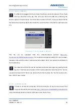
3. Calibrate the speed sensors: 

In order to achieve an accurate value, the calibration of the speed sensors should not be car-

ried out on smooth surfaces such as asphalt, if possible, but directly in the field.  

Ensure that the tractor for which the calibration is being carried out is active. Otherwise, a 

confirmation prompt opens as in Illustration 8-17. 

Содержание EXPERT 75

Страница 1: ...EXPERT 75 HW 1 0 User manual Version 1 0 04 08 2021 Kallinger Madeleine 487 679...

Страница 2: ...Overview of changes User manual EXPERT 75 HW 1 0 i Overview of changes Version Comment Date Name 1 0 Creation of initial version 18 05 2018 S Bilsing C Lenz...

Страница 3: ...ioning 3 2 3 Life span 4 2 4 Repair Maintenance 6 2 5 Disposal 7 3 1 The Expert 75 8 3 1 1 Front 9 3 1 2 Rear 11 3 1 3 Interface assignment 13 3 1 4 Fuses 14 3 2 Initial operation 14 3 2 1 Fitting 15...

Страница 4: ...24 4 4 4 CAN 25 4 4 5 GPS 25 4 4 5 1GPS info 25 4 4 5 2GPS settings 25 4 4 5 3Geometry settings 26 4 5 Info and diagnosis 27 4 5 1 Terminal 28 4 5 2 Network participants 28 4 5 3 Memory 29 4 5 4 Self...

Страница 5: ...7 3 Troubleshooting 51 8 1 Features 52 8 2 Operation 52 8 2 1 Basics of the tractor ECU 52 8 2 2 Initial operation 53 8 2 3 Main view of the panel app TECU 54 8 2 4 Select speed sensor 56 8 2 5 Set w...

Страница 6: ...bleshooting 72 9 1 Features 75 9 2 Operation 75 9 2 1 To view the available licences 75 9 2 2 Licence input 76 9 2 2 1Manual input 76 9 2 2 2Input via USB stick 78 9 2 2 3Automatic request 78 9 2 2 4E...

Страница 7: ...n view of the panel app Layout 37 Illustration 6 2 Start menu 38 Illustration 6 3 Layout context menu 39 Illustration 6 4 Detailed view of layout 39 Illustration 6 5 Pop up Widgets 40 Illustration 6 6...

Страница 8: ...ation 8 10 Tractor detail view Tractor settings 61 Illustration 8 11 Tractor detail view Tractor settings 61 Illustration 8 12 Select wheel sensor signal source 63 Illustration 8 13 Select radar senso...

Страница 9: ...pp Licence 76 Illustration 9 3 Licence input by hand 77 Illustration 9 4 Panel app Precision options 77 Illustration 9 5 Licence request on USB stick 78 Illustration 9 6 Successful licence entry 79 Il...

Страница 10: ...les Table 2 1 Hazard sign 2 Table 3 1 Explanation of the controls 10 Table 3 2 Explanation of the controls cont d 13 Table 3 3 Interface assignment 13 Table 7 1 panel App FS Troubleshooting 51 Table 1...

Страница 11: ...pplications and settings However should an error occur you will be given detailed advice here 1 1 Field of application This product is an operations terminal for use in agricultural engineering Its IS...

Страница 12: ...t state of these technologies when using installing storing and disposing of this device Particularly important safety relevant information is highlighted again below In addition haz ards are categori...

Страница 13: ...he increased use of electronic devices in agriculture means that disruptions can occur due to electromagnetic interference When installing electronic devices on a machine the installer must determine...

Страница 14: ...EMC standard and the corresponding directive The installation location in tended use and device connection must be carried out accordingly Caution The device should be placed at a sufficient distance...

Страница 15: ...temperatures 40 C 80 C and pro tect the connectors from contamination If any one of the following scenarios is detected then switch off the device in each case and do not use it any further To use th...

Страница 16: ...pening the casing is prohibited Doing otherwise will void the warranty as the device s pro tection class is no longer ensured and consequent damage to the device may occur If work is to be carried out...

Страница 17: ...Disposal The device must be disposed of in an environmentally friendly manner at the end of its service life To do so contact your dealer or a disposal centre Warning Environmentally sound disposal i...

Страница 18: ...t A light dependent resistor LDR measures the ambient light for this function When the night design is turned on the keys on the front panel are also illuminated The EXPERT 75 has a convenient power m...

Страница 19: ...als can be emitted via the integrated loudspeaker The volume is adjustable 3 1 1 Front Illustration 3 1 Front panel controls 1 Light dependent resistor ambient light sensor LDR The ambient light senso...

Страница 20: ...used to quickly switch between apps Exactly which apps are switched between can be configured individually Section 4 2 3 7 Acknowledge key The Acknowledge key is used to acknowledge warning and advis...

Страница 21: ...selection key The rotary impulse encoder is used for better navigation in the menu 11 Fixing thread M5 The device must always be installed using both fixing points 12 On Off key The on off key must be...

Страница 22: ...n addition to the two RS232 interfaces The signals from the tractor signal socket in accordance with ISO 11768 or separate sensors can be connected here The analogue input can detect a resolution of 0...

Страница 23: ...rey CAN 1 Low 6 GND pink GND 7 CAN0H blue CAN 1 High 8 Screen red Screen RS232 signal M12 x1 12pin socket for signal socket in accordance with ISO 11768 1 UB_SW brown Supply voltage interconnected 2 G...

Страница 24: ...ver the time needed for regeneration is strongly dependent on the ambient temperature There is no guarantee that the fuses will fully regenerate after the first trip Nevertheless the unit should be ab...

Страница 25: ...y only be bent in accordance with the data sheet Before any installation make sure the sealing rings are present in the sockets of the M12 connectors 3 2 2 Connection The power supply must be connecte...

Страница 26: ...nostics 4 1 Features The panel app Menu includes the following functions and features Sound and lighting configuration Configuration of a free assignable key1 Regional specific settings for text keybo...

Страница 27: ...with scroll wheel3 opens a pop up dialogue for activating deactivating the softkey selection via scroll wheel in UT screens Illustration 4 1 User settings Keypad lighting4 opens a dialogue in which t...

Страница 28: ...e Day and Night strategies are static and use the set illuminance levels for day and night The Auto strategy is dynamic and automatically switches between the illuminance levels for day and night depe...

Страница 29: ...Description Panel app Menu activated deactivated TC Task Controller activated deactivated 4 2 4 Keypad lighting Icon Description Illumination mode Off On Automatic sets the illumination strategy The O...

Страница 30: ...ts opens a dialogue in which the standard units used for the display of various parameters distance area volume etc can be selected See section 4 3 1 Number formats opens a pop up dialogue where a cho...

Страница 31: ...ction 4 4 1 App management opens a dialogue in which in dividual apps can be activated and deactivated Section 4 4 2 Interfaces opens a dialogue in which settings for various hardware interfaces can b...

Страница 32: ...ue to enable GPS related settings Section 4 4 5 Licence key opens a dialogue to display and activate the individual app licences See chapter 190 4 4 1 Date and time The following settings can be made...

Страница 33: ...ated deactivated Activated means summer Deactivated means winter am pm am pm specifies the addition for the time format Only for the 12hr time format 4 4 2 App management The app management lists all...

Страница 34: ...4 3 1 LAN settings DHCP activated deactivated activates the DHCP server IP address sets the address in the LAN Subnet mask sets the subnet mask Gateway sets the gateway address DNS server sets the DNS...

Страница 35: ...de the driver s cab 4 4 5 GPS GPS information can be displayed and GPS settings can be made in this dialogue 4 4 5 1 GPS info displays various information on GPS signal reception For example this info...

Страница 36: ...machine and navigation reference points A positive value represents a dis tance to the front and a negative value to the back NRP Offset B 10 10 describes the lateral distance between the machine and...

Страница 37: ...Section 4 5 2 Memory opens a resource monitor for the various device memories Section 4 5 3 Self test opens a dialogue on various device test functions Section 4 5 4 Error memory opens a dialogue tha...

Страница 38: ...ork participants A corresponding object pool can be found for each participant here The object pool for a machine is displayed even though it is not connected Machines that are not connected are indic...

Страница 39: ...4 5 3 Memory This section provides overviews of memory usage Main memory shows an overview of working memory usage Internal memory shows the usage overview of the internal flash storage medium USB st...

Страница 40: ...n be tested and displayed Scroll wheel opens a dialogue in which the scroll wheel function can be tested Loudspeaker opens a dialogue in which the loudspeaker function is tested A test sound is played...

Страница 41: ...sages on the CAN bus Start recording starts the recording of CAN messages in a log file Selection downwards No function Selection downwards No function Confirm selection acknowledges the selection End...

Страница 42: ...the same COM port is al ready used for another function The device is connected to a router via ethernet but no Internet connection is es tablished Check the IP address to see if the router and termin...

Страница 43: ...l of the attached machine on the terminal Connection and assignment of auxiliary controls Request behaviour according to ISO standard 11783 6 Manufacturer independent use for all attached machines tha...

Страница 44: ...n of the AUX input de vice Illustration 5 3 AUX Assignment in the User Settings After opening the AUX Assignment the current AUX functions assignment is shown cf Il lustration 5 4 Each list item shows...

Страница 45: ...is active an input option e g joystick or switch can be assigned to a se lected AUX function by pressing it directly Assigning then takes place automatically without having to select from the list If...

Страница 46: ...is played In this case check whether the software can be started from the terminal start menu There is a connection error when the at tached machine software is being loaded onto the terminal Check th...

Страница 47: ...s the following features Create and manage multiple screen layouts that are available as individual desktops Simultaneous display of information from different panel apps as well as attached ISO BUS d...

Страница 48: ...keys The layout context menu cf Illustration 6 3 opens for the layout se lected from the list A new layout is created and the detailed view of the new layout opens All created layouts are deleted Ther...

Страница 49: ...mmodate widgets and twelve softkey cells one column each on the right and left to accommodate widget keys A cell for widgets is 240x80 pixels a cell for a widget key is 80x80 pixels Widgets are object...

Страница 50: ...layout Detail view of the next layout opens If the last layout in the layout list is currently displayed a new layout is created and the detailed view of the new layout is opened Detailed view of the...

Страница 51: ...the main area and assign the desired widget key to the list cf Illustration 6 6 Illustration 6 7 shows a layout after the panel app TECU speed display has been placed in the left column of the first r...

Страница 52: ...d can be accessed via the start menu Illustration 6 9 Desktop for My Layout 1 All created screen layouts are permanently stored on the terminal The associated desktops are adapted when the terminal is...

Страница 53: ...e for the widget Se lect another cell in the grid that has the appropriate space The machine to be displayed is not connected Con nect the machine An empty area is displayed on the desktop of the sele...

Страница 54: ...pp FS is activated 7 1 Features The panel app FS has the following functions Information display such as connection details open files and memory allocation A file manager for managing folders and fil...

Страница 55: ...tration 7 2 Memory data Illustration 7 2 shows the memory allocation information The total amount of memory cur rently available in the internal and external memory what s allocated and what s still f...

Страница 56: ...nd the external memory can be made here Note The external memory can only be selected if a USB stick is connected to the terminal Illustration 7 4 File manager Internal memory The file manager interna...

Страница 57: ...Illustration 7 5 New folder Enter the folder name Illustration 7 6 The new folder is created When you create a new folder an input window opens next Illustration 7 5 Enter the name of the folder here...

Страница 58: ...he folder 4 If you want to delete the folder a confirmation window is displayed first see Illustration 7 8 5 If there are files or subfolders in the folder they are also deleted 6 After pressing OK de...

Страница 59: ...le Illustration 7 9 File display in the file manager Pressing on the file opens the selection window Illustration 7 10 By selecting Information further information on the file appears This can be seen...

Страница 60: ...on Illustration 7 12 Prompt to confirm the deletion 7 2 5 Detailed view of files currently open The panel app FS provides a detailed view of files currently open This can be reached via the main windo...

Страница 61: ...l A file or folder cannot be deleted This can occur if a file is currently opened us ing another application Ensure that the file is not currently opened from any applica tion You can check this in th...

Страница 62: ...Forwarding tractor data to attached ISOBUS machines Selection of sensor sources and calibration of the sensors Manage multiple tractors and their settings in a tractor database Active and passive mod...

Страница 63: ...re forwarded to attached ISOBUS machines If the tractor has a primary TECU or a higher priority TECU that provides the tractor infor mation via ISOBUS the panel app TECU switches to passive mode The d...

Страница 64: ...ition of the rear hoist A signal cable is required to connect the terminal to the signal socket Connect the Signal interface on the rear of the terminal to the tractor signal socket 8 2 3 Main view of...

Страница 65: ...g operating options via the softkeys Edit active tractor F2 Select speed sensor F4 Set working position F6 Show tractor list F8 Activate documentation and task management F10 Show hectare counter F12...

Страница 66: ...nsor is selected Radar sensor is selected To switch between the speed sensors select the softkey F4 Select speed sensor The icon in the main view adapts accordingly 8 2 5 Set working position The lowe...

Страница 67: ...t the current position of the 3 point as the limit value for the working position select the softkey Set working posi tion for the selected 3 point position The percentage value corresponding to the 3...

Страница 68: ...This is identified by the tractor symbol in the upper right corner of the second field In this display the function keys provide the following operating options A new tractor can be created and the d...

Страница 69: ...inal tractor accompanied by the word Copy This name can be changed in the tractor settings The selected tractor is deleted A confirmation prompt occurs before deleting such as in Illustration 6 6 The...

Страница 70: ...t and 3 point linkage is not available in the Tractor settings tab or the signal socket is not set as the source If the signal socket is se lected as the source for one of these sensors in the tractor...

Страница 71: ...d radar sensor PTO shaft sensor 3 point sensor power management and X sensor cf Il lustration 8 10 and Illustration 8 11 Illustration 8 10 Tractor detail view Tractor set tings Illustration 8 11 Tract...

Страница 72: ...from the list of tractor settings In the text input field that opens change the tractor name and confirm with OK 2 Select signal source The possible choices of signal sources for wheel sensor radar se...

Страница 73: ...you have set the signal socket as the signal source for the 3 point sensor you must calibrate the 3 point You can execute the calibrations in the relevant tractor detail view tab 3 Activate Power Man...

Страница 74: ...a tion 8 14 and Illustration 8 15 Illustration 8 14 X sensor security prompt Illustration 8 15 Activate X sensor 8 2 7 4 Speed In the Speed tab set the speed sensor to record the tractor speed Both sp...

Страница 75: ...s for the number of pulses per 100 metres is between 200 and 30000 The more accu rate this value is the more precise the speed display is in the main view If the value for the number of pulses per 100...

Страница 76: ...ve when both speed sensors are used simultaneously To set the hectare counter source select the Hectare counter priority button from the Speed tab From the selection list that opens select the wheel s...

Страница 77: ...e wheel sensor or the radar sen sor for calibration Drive to the starting point of the section and press the function key F3 Start flag cf Illustration 8 19 Drive the 100 metre section and press the f...

Страница 78: ...a new tractor is added then a value of 6 pulses per 100m is preset The effective range of values for the number of pulses per revolution is between 1 and 40 The value to be entered for your tractor c...

Страница 79: ...calibration is being carried out is active Otherwise a confirmation prompt opens To calibrate the 3 point sensor proceed as follows Select the function key F3 Calibrate in the 3 point linkage tab Rai...

Страница 80: ...are not plausible an error message is displayed 8 2 8 Show hectare counter If you select the softkey F12 Show hectare counter in the main view you have the oppor tunity to display process data for an...

Страница 81: ...counter F4 Reset distance counter F5 Reset area counter F6 If one of these softkeys is pressed the corresponding counter is reset to 0 and the display is updated In addition the working width of the a...

Страница 82: ...her TECU on the ISOBUS is indicated by a blue frame and the blue letter i However connection to the signal socket is only necessary if not all tractor information is provided via the ISOBUS In this ca...

Страница 83: ...length of the section Check that the sensor is intact Repeat the calibration process Calibration error Invalid value The max position is approx 0V Please check the sensor and the 3 point position and...

Страница 84: ...Tractor ECU panel app TECU User manual EXPERT 75 HW 1 0 74 TECU error Connection to control failed panel app TECU could not connect to panel app TC Check the Task Controller status...

Страница 85: ...oes not offer a licences purchasing function Licence information transfers to the terminal must be initiated by the user or after the purchase of a licence 9 2 Operation 9 2 1 To view the available li...

Страница 86: ...lable because it has been approved 9 2 2 Licence input The following interaction options are available Manual licence information input is done by pressing the F3 key Licence information input via USB...

Страница 87: ...at the website mentioned can be entered Its form is also 5 times 8 characters XXXXXXXX XXXXXXXX XXXXXXXX XXXXXXXX This activation code is only valid at the terminal of whose request code the release c...

Страница 88: ...website https iso bus sdnord de ANDSP publicactivation The activation code generated by this can be down loaded as a file with the name terminal serial number SP liz and copied to a USB stick in the t...

Страница 89: ...e licence information for the terminal is valid a positive result is displayed see Illustration 9 6 Illustration 9 6 Successful licence entry If the manually entered key is invalid due to a typing err...

Страница 90: ...d The strip next to the button is grey The USB stick was not recognised by the terminal or a USB stick wasn t inserted at all Ensure that the desired USB stick is inserted in the USB socket on the ter...

Страница 91: ...the terminal serial number matches the serial number on the website https iso bus sdnord de ANDSP publicactivation given during the request Only enter the dis played activation code on the terminal w...

Страница 92: ...ccur due to incorrect operation con figuration or device connection Aided by the measures presented the user can carry out trou bleshooting and rectification themselves However in general if a problem...

Страница 93: ...r tractor and try to restart your device The terminal does not re spond to the ignition signal Make sure that the power management is acti vated on your control unit and that the tractor s ig nition s...

Страница 94: ...lementation level IL4 Conformance Test 2010 Operating functions Board front FR4 Strength 1 6 mm Night design Luminous foil that illuminates the back of the keys when required Decorative foil Screen pr...

Страница 95: ...g third party software components are used Expat Copyright c 1998 2000 Thai Open Source Software Center Ltd and Clark Cooper Copyright c 2001 2006 b64 Copyright c 2001 Trantor Standard Systems Inc Har...

Страница 96: ...Annex Declaration of Conformity User manual EXPERT 75 HW 1 0 86 13 Annex Declaration of Conformity...

Страница 97: ...de 2021 by ANEDO 49406 Eydelstedt All rights re served The information given is for product description purposes only A statement about a certain condition or the suitability for a certain purpose ca...

Отзывы: