background image

2

912.822.1 - GB

InstructIons pertaInInG to the user

Dear Customer,

We are sure your new boiler will comply with all your requirements.

Do not dispose of this booklet. This manual contains the information, which will help you to 

run your boiler correctly and efficiently.

potterton coMMercIaL

 boilers bear the CE mark in compliance with the basic 

requirements as laid down in the following Directives:

- Gas Directive 90/396/EEC
- Efficiency Directive 92/42/EEC
- Electromagnetic Compatibility Directive 2004/108/EEC
- Low Voltage Directive 2006/95/EC

Do not leave any parts of the packaging (plastic bags, polystyrene, etc.) within children’s reach as they are a 

potential source of danger.

ATTENTION

This boiler can only be installed and operate

in permanently, ventilated rooms in accordance with

BS6644

Содержание Sirius two FS 50

Страница 1: ...Working towards a cleaner future Sirius FS 50 70 Floor Standing Condensing Gas Boilers Installation Operation Maintenance Manual To be kept by the user October 2010 heating specialists ...

Страница 2: ...rs bear the CE mark in compliance with the basic requirements as laid down in the following Directives Gas Directive 90 396 EEC Efficiency Directive 92 42 EEC Electromagnetic Compatibility Directive 2004 108 EEC Low Voltage Directive 2006 95 EC Do not leave any parts of the packaging plastic bags polystyrene etc within children s reach as they are a potential source of danger ATTENTION This boiler...

Страница 3: ... installation 13 10 Boiler installation and dimensions 14 11 Chimney flue connection 21 12 Connecting the mains supply 23 13 Adjusting the gas valves and gas change 30 14 Setting the boiler parameters 32 15 Control and operation devices 34 16 Positioning of the ignition and flame sensing electrode 35 17 Check of combustion parameters 35 18 Activating the chimney sweep function 36 19 Annual service...

Страница 4: ...f solder and solvents if any using suitable proprietary products To avoid damaging metal plastic and rubber parts use only neutral cleaners i e non acid and non alkaline The recommended products for cleaning are SENTINEL X300 or X400 and FERNOX heating circuit restore The use of this product must be strictly in accordance with the maker s directions Finally the system must be dosed with a suitable...

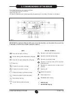
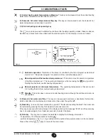
Страница 5: ...resent on Outdoor temperature Standby off Operation in manual mode at minimum tem perature Operation in manual mode at the maximum temperature set Operation in automatic mode Operation in central heating mode Operation in domestic hot water mode 020503_1100 Figure 1 IMPORTANT Domestic Hot Water D H W instructions discribed here are to be taken into account only if the boiler is connected to a D H ...

Страница 6: ...in point 3 7 Faults and resetting the boiler the boiler can be restarted by pressing this key for at least two seconds see 3 8 If this key is pressed with no fault present the display will show the message E153 and the same key has to be pressed again for at least two seconds to restart the boiler 9 Data key This key can be pressed repeatedly to display the following information Temperature C of t...

Страница 7: ... the central heating water temperature Press the keys to set the temperature required Press either of the keys 1 or 10 figure 1 to save and return to the main menu N B With the outdoor sensor connected the key 2 figure 1 can be used to shift the central heating curve Press the keys to decrease or increase the room temperature in the premises to be heated 3 3 setting the maximum central heating tem...

Страница 8: ...estic hot water mode operation Factory setting of D H W function is enable ON while is disabled D H W daily times program To enable D H W daily times program see section 14 parameter H91 Setting the daily times for domestic hot water mode operation Carry out the operations described in section 3 5 1 for program lines 31 to 36 3 6 setting the minimum central heating temperature Press either of the ...

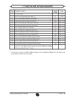
Страница 9: ... third daily period of automatic central heating Start of first daily period of domestic hot water production End of first daily period of domestic hot water production Start of second daily period of domestic hot water production End of second daily period of domestic hot water production Start of third daily period of domestic hot water production Fine End of third daily period of domestic hot w...

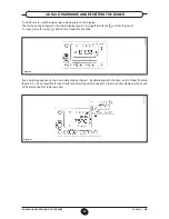
Страница 10: ...ure 4 To reset press the reset button for at least two seconds 020503_0500 Figure 4 020503_0600 Figure 4 1 Fault warnings appear on the secondary display figure 1 b alternating with the time both of them flashing figure 4 1 It is not possible to reset malfunction warnings which appear on the secondary display as the cause of the alarm has first to be removed 3 8 fault warnings and resetting the bo...

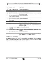
Страница 11: ... current If symbol is displayed press the reset button otherwise switch off the electricity supply to the boiler for at least 10 seconds if the fault persists call the authorised service centre Check the positioning of the ignition and flame sensing electrode see section 16 Press the key again about 2 seconds Press and hold reset button 2 seconds approx then press again when warning E153 appears C...

Страница 12: ...inhibitors The electronic management of the boilers includes a frost protection function in the central heating system which operates the burner to reach a heating flow temperature of 30 C when the system heating flow tempe rature drops below 5 C The frost protection function is enabled if electrical supply to the boiler is on the gas service cock is open the system pressure is as required the boi...

Страница 13: ...d to Service Engineers to help them carry out a faultless installation Instructions regarding lighting and operation of the boiler are contained in the Instructions pertai ning to the user section Note that installation maintenance and operation of the gas appliances must be performed exclusively by qualified personnel in compliance with current standards Please note the following Install the boil...

Страница 14: ... the following precautions 1 Heating circuit 1 1 New system Before proceeding with installation of the boiler the system must be cleaned and flushed out thoroughly to eliminate residual thread cutting swarf solder and solvents if any using suitable proprietary products To avoid damaging metal plastic and rubber parts use only neutral cleaners i e non acid and non alkaline The recommended products ...

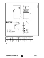
Страница 15: ...ing Fitting Water contents mm mm mm fitting F R l A CH CH FS 50 621 850 450 G 3 4 G 1 G 1 5 1 FS 70 693 850 450 G 3 4 G 1 G 1 6 5 MR heating flow RR heating return GAS gas inlet to the boiler SC condensate drain Insert the flue gas union and fasten the connector to the flue gas thermo stat CT_0804 0906_3005 ...

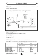
Страница 16: ...ied with the boiler P1 Heating Pump PDHW Hot Water Pump PLP Primary Pump Available Optional Extra Pumps Hot Water Cylinder Low Loss Header Non return valve Not supplied Installer Wiring Applications pumps sensor remote control have to be connected to terminal as follows see also section 12 WITH QAA73 WITH REMOTE CONTROL ROOM THERMOSTAT APPLICATION TERMINAL BOARD TERMINAL BOARD PRIMARY PUMP PLP M1 ...

Страница 17: ...h remote control QAA73 including hot water tank with primary loop Applications and Installation Details TS Tank Sensor QAZ36 B3 Room Control Module QAA73 B1 Room Thermostat B9 Outdoor Temp Sensor QAC34 supplied with the boiler AGU2 500 Zone controller Clip in AGU2 500 FS Flow Sensor QAD36 supplied with the AGU2 500 P1 CTC Heating Pump P DHW Hot Water pump PLP Primary Pump 3WV 3 Way Valve power ope...

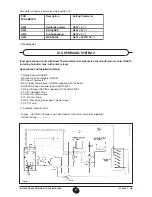
Страница 18: ...eter changes requires see also section 14 PCB PARAMETER Description Setting Parameter H552 Hydraulic system H552 50 H553 KonfigHKS H553 12 H615 KonfigAusgang H615 9 H632 WANFO Q8 00001111 10 3 HYDRAULIC SYSTEM 3 Cascade with pumped heating circuits Room Thermostats primary loop Applications and Installation Details RT Room Thermostat B9 Outdoor Temperature Sensor QAC34 supplied with the boiler OCI...

Страница 19: ...HERMOSTAT RVA 47 FLOW RETURN SENSOR QAD 21 RVA 47 Parameter changes requires see also section 14 PCB PARAMETER Description Setting Parameter H552 Hydraulic system H552 80 H553 KonfigHKS H553 21 H615 KonfigAusgang H615 9 H632 WANFO Q8 00001111 If DHW circuit is required then DHW pump and DHW sensor have to be connected to terminal of RVA 47 Cascade Controller For more details refer to the instructi...

Страница 20: ...it sec kPa Lit sec kPa Lit sec kPa Lit sec FS 50 50 0 97 32 0 71 25 0 53 10 0 35 FS 70 60 1 41 35 1 03 20 0 77 11 0 51 Boiler Hydraulic Resistance and Water Flow Rates 11 K T 15 K T 20 K T 30 K T FS 50 0 27 FS 70 0 33 Boiler Minimum Water Flow Rates Lit sec Exchangers pressure drop mH 2 O WATER FLOW RATE l h Graph 1 0712_0903 ...

Страница 21: ...le use a flue connection that can be disconnected for maintenance Important Horizontal flue sections must have a minimum slope of 3 towards the boiler Flue accessories made of plastic material for cascade or single installations are available 11 chimney flue connection CT_0810 0902_2703 Figure 7a 0712_0905 CT_0752 Max length of flue duct model HTE 45 30 m L Max length of flue duct model HTE 65 20 ...

Страница 22: ...d to introduce combustion air from outside the installation area and comprises a hose to be installed in the mixer body Please consult the instructions supplied with the kit For air ducts diameter and length see the kit manual 11 2 Connector with C53 type CT_0813 0903_0601 ...

Страница 23: ...the appliance is less than 2 amp If the value is greater a relay must be wired between the boiler control circuit board and the accessories drawing the higher current 12 1 terminal blocks access Isolate power to the boiler with the two pole switch Remove the top facia panel cover which is held by magnets Unscrew the two screws holding the facia panel in place Swing the facia panel forwards Main te...

Страница 24: ... the pump must be as follows 230 V AC 50 Hz 1 A max cos f 0 8 If the specifications of the installed pump are different a relay must be wired between the boiler control circuit board and the pump It is advisable not to adopt any electrical connection other than those described Connect earth to earth strip Remove the resistor from terminals 9 10 of terminal strip M2 figure 12 and connect the hot wa...

Страница 25: ...25 912 822 1 GB Instructions pertaining to the installer Figure 12 external power input 0 10V 0602_0707 CG1764 0602_0708 CG1765 safety contact room thermostat Figure 13 ...

Страница 26: ... connection to signal lamp 230 V 0 5 A max for lockout alarm Terminals 5 6 L N OUT connection to signal lamp 230 V 0 5 A max for run mode Terminals X51 1 2 connection to external power input 0 10 V pin 1 positive power input pin 2 negative power input For low voltage signal lamp remove the internal wiring and feed with an external low voltage power supply 12 4 description of the electrical connect...

Страница 27: ...or the central heating circuit of the other zones can be set directly on the boiler control panel See the instructions provided with the QAA73 temperature regulator for the user parameter programming procedure QAA73 parameters which can be set by the installer service By pressing the two PROG buttons together for at least three seconds it is possible to access the list of para meters that the inst...

Страница 28: ... Type of building Room compensation Activation deactivation of the influence of the room temperature If it is deactivated the outdoor temperature sensor must be installed Automatic adaptation of the temperature curve kt in relation to the room temperature Opt Start Max Maximum time the boiler is switched on ahead of the timed program to optimise the temperature in the premises Opt Stop Max Maximum...

Страница 29: ...entral heating b With QAA73 room temperature regulator The temperature curve kt must be selected by setting parameter 70 HC1 curve of the QAA73 room tem perature control device as described in section 12 4 QAA73 parameters which can be set by the installation service engineer See graph 4 for selecting the curve referred to a room temperature of 20 C The curve is shifted automatically on the basis ...

Страница 30: ...the installer 13 adjusting the gas valves Figure 14 LEGEND Pi Gas supply pressure connection point P out Pressure connection point for measurement of the OFFSET V Gas flow adjuster screw K OFFSET adjuster screw 0712_0912 CT_0754 Mixer Gas valve ...

Страница 31: ...until you achieve the CO2 levels shown in table 2 1 for natural gas G20 and in table 2 2 for propane LPG Turn the screw anti clockwise to increase the CO2 level Turn the screw clockwise to decrease the CO2 level Press the key to set the minimum heat output with the display showing 0 figure 13b Remove the protection cap and turn the adjuster screw K on the gas valve until you achieve the CO2 levels...

Страница 32: ...heat output 8 4 8 4 Parameters H536 H613 rpm at maximum power 6100 6400 Parameters H541 H610 pwm at maximum power 85 100 Parameter H612 rpm at minimum power 1700 1450 Parameter H609 pwm at minimum power 13 5 11 Parameter H611 rpm ignition load 2600 2500 Parameter H608 pwm ignition load 20 18 Gas consumption at 15 C 1013 mbar Gas G31 3P 37 mbar 50 70 PCI MJ kg 46 34 46 34 Consumption at max heat ou...

Страница 33: ...ve of central heating circuit HC2 see Graph 2 PWM Setting Ignition load Speed setting rpm Ignition load PWM Setting minimum power PWM Setting maximum power Central heating Domestic hot water Speed setting rpm minimum power Speed setting rpm maximum power Central heating Domestic hot water Pump post circulation time in central heating mode min Burner operating pause time between two start ups s Hyd...

Страница 34: ...mplete interlighting of the main burner Under such conditions the boiler is locked out You must press the reset button on the boiler to restore the normal operating conditions Pump overrun The electronic control system keeps the pump operating for 10 minutes in central heating mode after the room temperature thermostat has switched off the main burner Frost protection device The boilers electronic...

Страница 35: ...centration Carbon monoxide CO concentration Measure the temperature of combustion air near the air inlet to the boiler The necessary hole must be made by the technician responsible for the heating system when the system is first started up and must then be closed to ensure that the flue remains properly sealed during normal operation 17 check of combustion parameters Figure 17 Figure 16 16 positio...

Страница 36: ...0200 Figure 18 To ensure the boiler operates at peak efficiency the following checks must be performed every year Check on the appearance and tightness of the gas and combustion circuit gaskets Check on the condition and position of the ignition and flame sensing electrodes see section 16 Check on the condition of the burner and its fixing to the aluminium flange Check for any dirt in the combusti...

Страница 37: ...t 5 Gas valve 6 Heat exchanger 7 Flame detector electrode ionisation probe 8 Burner 9 Ignition electrode 10 Mixer with venturi 11 Air gas diaphragm 12 Fan 13 Flue joint 14 Automatic air vent 15 Hydraulic pressure sensor 16 Boiler drain point 17 Joint flue with flue thermostat 18 Flue thermostat 19 Gas pressure switch 20 Seat of air intake 20 boiler schematic CT_0817 0906_2401 ...

Страница 38: ...38 912 822 1 GB Instructions pertaining to the installer 21 illustrated wiring diagram CT_0756 0906_2206 ...

Страница 39: ...type B23 B23P C53 Flue duct diameter mm 80 80 Max flue mass flow rate kg s 0 022 0 031 Min flue mass flow rate kg s 0 006 0 007 Max flue temperature C 72 73 NOx class 5 5 Type of gas used G20 G20 G31 G31 Natural gas feeding pressure 2H mbar 20 20 Propane gas feeding pressure 3P mbar 37 37 Gas Consumption NG m3 hr 4 91 7 08 Minimum Operating Pressure Bar 1 1 High Level Ventilation to BS6644 boiler ...

Страница 40: ...LL Tel 0844 871 1540 Applications Installations Our experienced technical support team are available to offer advice on any aspect of heating system design and boiler installation Please contact 0845 070 1057 Commercial service offices Our service organisation covers the whole of the UK to look after your needs for all Potterton Commercial products Our service office offers a wide range of special...

Отзывы: