background image

PROVISOIRE

15

28/08/2012 - 300029292-001-02

NXR3i

4.5 Hydraulic connections

4.5.1

Flushing the system

„

Installing the boiler in new installations 
(installations less than 6 months old)

`

Clean the installation with a universal cleaner to eliminate
debris from the appliance (copper, hemp, flux).

`

Thoroughly flush the installation until the water runs clear and
shows no impurities.

„

Installing the boiler in existing installations

`

Remove sludge from the installation.

Z

See: Sludge removal.

`

Flush the installation.

`

Clean the installation with a universal cleaner to eliminate
debris from the appliance (copper, hemp, flux).

`

Thoroughly flush the installation until the water runs clear and
shows no impurities.

4.5.2

Sludge removal

A tapped Rp 2" 1/2 hole with a plug has been provided on the bottom
of the front of the boiler.. Fit a 1/4 turn valve (not supplied) on the
opening to remove the sludge.
Sludge removal leads to the draining of large quantities of water, so
remember to refill the system after the operation.

After this operation, go ahead and fill the installation.

Z

See: Filling the system.

never replace a boiler in an existing system without carefully
rinsing the system first. Install a sludge decanting pot on the
return pipe, very close to the boiler.

4.5.3

Hydraulic connection of the heating circuit

„

Water flow in the boiler

The water flow in the boiler when the burner is operating must
correspond with the following formulae:
- Nominal water flow Qn = 0.86 Pn/20.
- Minimum flow Qmin = 0.86 Pn/45 (this flow also corresponds with

the minimum recycle flow in the boiler).

- Maximum water flow Qmax = 0.86 Pn/5.

Qn = flow in m

3

/h.

Pn = Nominal output (full boiler output) in kW.

Connect the flow controller to the terminal blocks 

UV

 in the

control panel KSF CE.

Connect the flow switch to 

Q

 between terminals 

SK1

 and 

SK2

on the KSF ISR control panel.

„

Operation in cascade

After stopping the burner:
- Timeout required before the order to close a 2 way valve: 3 min.
- Switch a possible shunt pump (located between the boiler and a

butterfly valve) off via the end of run contact of the butterfly valve.

„

Operation with 2-stage burner

- The water temperature in the boiler is maintained at 50°C or more;

The first stage must be set to a minimum of 30% of the nominal
stage.

- Operation at modulated low temperature (minimum outlet

temperature: 30°C); The first stage must be set to a minimum of
50% of the nominal stage.

Z

Refer to the installation and service manual for the KSF CE

control panel.

„

Operation with modulating burner

- The water temperature in the boiler is maintained at 50°C or more:

The burner can modulate down to 30% of the nominal stage.

- Operation at modulated low temperature (minimum outlet

temperature: 30°C); The burner can modulate down to 50% of the
nominal stage.

Z

Refer to the installation and service manual for the KSF ISR

control panel.

Содержание NXR3i

Страница 1: ...Working towards a cleaner future NXR3i Fuel oil gas boilers Installation and Service Manual To be kept by the user May 2013 heating specialists ...

Страница 2: ...eclaration of conformity CE The appliance complies with the standard model described in declaration of compliance 1 It is manufactured and distributed pursuant to the requirements of european directives The original of the declaration of compliance is available from the manufacturer ...

Страница 3: ...e location 10 4 3 1 Main dimensions 10 4 3 2 Position of the boiler 11 4 3 3 Ventilation 12 4 4 Example of an installation 13 4 5 Hydraulic connections 15 4 5 1 Flushing the system 15 4 5 2 Sludge removal 15 4 5 3 Hydraulic connection of the heating circuit 15 4 5 4 Safety valve 16 4 5 5 Connection of the water circuit for domestic use 16 4 6 Chimney connection 17 4 6 1 Flue size 17 4 6 2 Connecti...

Страница 4: ... 02 7 3 1 Cleaning the flue gas circuit 21 7 3 2 Cleaning the combustion chamber 21 7 3 3 Positioning of the baffle plates 22 7 3 4 Cleaning the flue gas box 23 7 3 5 Chemical sweeping 23 7 4 Cleaning the casing material 24 7 5 Maintenance of the burner 24 8 Spare parts NXR3i 25 ...

Страница 5: ...tions on using the appliance Faulty or insufficient maintenance of the appliance Failure to abide by the instructions on installing the appliance 1 2 2 Installer s liability The installer is responsible for the installation and inital start up of the appliance The installer must respect the following instructions Read and follow the instructions given in the manuals provided with the appliance Car...

Страница 6: ...nd hot water tanks with a maximum operating pressure of 10 bar pertain to article 3 3 of the directive and therefore cannot be CE marked to certify compliance with the directive 97 23 EC The boilers and hot water tanks are designed and manufactured in accordance with the sound engineering practice as requested in article 3 3 of the directive 97 23 EC it is certified by compliance with the directiv...

Страница 7: ...6 Inform the gas supplier 2 1 2 Risk of intoxication Do not obstruct the air inlets in the room even partially If you smell flue gases 1 Switch the appliance off 2 Open the windows 3 Evacuate the premises 4 Contact a qualified professional 2 1 3 Risk of being burnt Depending on the settings of the appliance The temperature of the flue gas conduits may exceed 60 C The temperature of the radiators m...

Страница 8: ...t 110 C Boiler NXR3i 4 NXR3i 5 NXR3i 6 NXR3i 7 NXR3i 8 NXR3i 9 Useful output kW 70 105 105 140 140 180 180 230 230 280 280 330 Power input kW 76 117 115 156 153 199 197 253 252 309 305 361 Water content l 96 116 136 156 176 196 Number of sections 4 5 6 7 8 9 Stand by losses 50 C A 0 17 0 14 0 13 0 11 0 10 0 09 Number of baffle plates 6 10 10 6 6 6 Water resistance T 15K mbar B 6 2 10 9 20 4 30 44 ...

Страница 9: ...ns situated inside residential buildings and their annexes NF P 45 204 standards Gas installation formerly DTU 61 1 gas installations April 1982 addendum no 1 July 1984 Local Sanitary Regulations For appliances connected to the electricity network NF C 15 100 standards Low voltage electrical installation Rules Establishments open to the public Statutory terms and conditions of installation The ins...

Страница 10: ...it Heating flow Flange Counter flange with collar to be welded orifice Ø 2 1 2 Option Ø 2 Heating return Flange Counter flange with collar to be welded orifice Ø 2 1 2 Option Ø 2 Rp 1 1 2 draining outlet plugged Mk Tapped connection 1 Adjustable feet Basic dimension 0 mm adjustment possible 0 to 40 mm Boiler NXR3i 4 NXR3i 5 NXR3i 6 NXR3i 7 NXR3i 8 NXR3i 9 L mm 991 1151 1311 1471 1631 1791 P mm 490...

Страница 11: ...n If the boiler location is not determined precisely leave enough space around the boiler to facilitate monitoring and maintenance operations The dimensions in mm correspond to the minimum recommended dimensions needed to ensure adequate accessibility around the boiler Pay attention to the overall volume of the burner when the door is open To install several boilers in cascade these dimensions sho...

Страница 12: ...orroded by such chloride or fluoride compounds the contractual guarantee cannot be applied France The minimum cross sections and the emplacement of the fresh air inlet and the air discharge are governed by the order of 21 03 1968 amended by the orders of 26 02 1974 and 03 03 1976 Generator installed in a building for collective use installations less than 70 kW The fresh air inlet must Come out in...

Страница 13: ...elow does not cover every possible configuration Its sole aim is to draw your attention to the basic rules to be respected NXR3i boiler with domestic hot water production using an independent tank L000047 9 2 14 12 17 11 27 9 56 32 9 10 1 9 57 9 27 26 15 9 17 18 9 19 20 9 17 16 13 3 7 9 7 30 28 9 29 27 9 31 5 6 9 9 9 ...

Страница 14: ... Water low safety pressure sensitive switch 15 Shunt pump 16 Expansion vessel 17 Drain cock 18 Heating circuit filling with disconnector depending on prevailing regulations 19 Water treatment 20 Water meter 26 DHW load pump 27 Non return valve 28 Domestic cold water inlet 29 Pressure reducer if mains pressure 5 5 bar 30 Sealed safety unit calibrated to 7 bar with indicator type discharge 31 Indepe...

Страница 15: ...ow in the boiler The water flow in the boiler when the burner is operating must correspond with the following formulae Nominal water flow Qn 0 86 Pn 20 Minimum flow Qmin 0 86 Pn 45 this flow also corresponds with the minimum recycle flow in the boiler Maximum water flow Qmax 0 86 Pn 5 Qn flow in m3 h Pn Nominal output full boiler output in kW Connect the flow controller to the terminal blocks UV i...

Страница 16: ...erposed between it and the boiler Minimum safety valve flowrate as a function of maximum boiler nominal output Example Maximum boiler nominal output is 200 kW Minimum safety valve flowrate must be 700 kg h 4 5 5 Connection of the water circuit for domestic use ZSee Domestic hot water calorifier instructions Minimum relieving capacity Maximum gross boiler output Unit a kW b lb h c MBtu h d Kg h ...

Страница 17: ...oved resulting in an insrease in the flue gas temperature 4 6 1 Flue size Refer to applicable regulations while determining the size of the flue Please note that NXR3i boilers have pressurised and tight furnaces and that the pressure at the nozzle must not exceed 0 mbar unless special sealing precautions have been taken for instance in order to connect a static condenser regenerator In order for t...

Страница 18: ...illing included shunt pump s Do not add cold water suddenly into the boiler when it is hot VERY IMPORTANT Instructions for starting up the boiler for the first time after the system is fully or partly drained If all the air is not bled naturally to an expansion vessel which opens out onto the air the system must include manual bleeder valves in addition to automatic bleeder valves with the capabil...

Страница 19: ... the case of long boiler stops The boiler and the chimney must be swept carefully Close all the doors of the boiler to prevent air from circulating inside the boiler We advise removing the pipe which connects the boiler to the chimney and to close off the nozzle with a cover 6 2 Precautions required if the heating is stopped when there is a risk of freezing We recommend the use of a correctly dose...

Страница 20: ...d be required only a few times in each heating season with very low quantities of water otherwise look for the leak and repair it 7 1 2 Draining We advise you against draining the system unless it is absolutely necessary For example Several months absence with the risk of ice in the building 7 2 Data plate The rating plate fixed on the side of the boiler during installation is used to identify the...

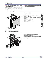
Страница 21: ...leaning the flue gas circuit Unhook the front panel Open the cleaning door top door by unscrewing the 4 closing nuts 17 mm spanner Remove the baffle plates Carefully sweep the flue ways with the brush supplied for that purpose Also sweep the baffle plates and the front panel If possible use a vacuum cleaner Replace the baffle plates Close the doors 7 3 2 Cleaning the combustion chamber Unscrew the...

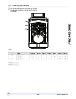
Страница 22: ... plates in the 2 lower flue ways are fitted with stops allowing them to be positioned in the required emplacement 1 Stop 1 4 baffles are not used 2 2 baffles are not used L000050 Baffles Flue ways NXR3i 4 NXR3i 5 NXR3i 6 NXR3i 7 NXR3i 8 NXR3i 9 Upper Length 410 mm A B 8 8 Length 570 mm A B 4 4 1 4 1 4 1 Lower Length 412 mm C 2 2 2 2 2 2 2 2 ...

Страница 23: ... must be suitable for boilers with a cast iron body Various manufacturers offer products in the form of a concentrated liquid or aerosol The aerosols are packaged in 0 5 to 1 l spray cans for treating domestic boilers Refer to the instructions supplied with the product The liquid products are available in 1 to 50 l containers These concentrated liquids are diluted before application with a spray S...

Страница 24: ...n the heating surfaces A volume of one litre of solution is generally used for 1 m2 of heating surface domestic boiler i e 0 05 to 0 2 l of concentrate Ignition The burner is ignited after allowing the product time to penetrate for 2 to 5 min Refer to the instructions supplied with the product Cleaning Remove the baffle plates Light sweeping will remove the pulverent residues remaining after combu...

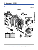
Страница 25: ...nterpart Brooks House Coventry Road WARWICK CV34 4LL 08706 000454 08706 000545 8 Spare parts NXR3i To order a spare part quote the reference number next to the part required 300029292 002 01 Boiler body 8553N059 C ...

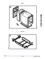
Страница 26: ...26 NXR3i 28 08 2012 300029292 001 01 PROVISOIRE NXR3i 28 08 2012 300029292 001 02 Insulation Base frame 12x 90 8553N061A ...

Страница 27: ...PROVISOIRE 27 28 08 2012 300029292 001 02 NXR3i Casing 108a L000053 ...

Страница 28: ...R3i 28 08 2012 300029292 001 01 PROVISOIRE NXR3i 28 08 2012 300029292 001 02 Control panels ZRefer to the Spare Parts list in the panel instructions KSF ISR control panel KSF CE control panel L000054 L000067 ...

Страница 29: ...door 23 9425 0302 Furnace door guard 24 9425 0301 Furnace door insulation 25 8015 7700 Sight glass gaskets 26 9757 0027 Inspection flange 27 9495 0050 Plug 1 4 28 8219 0539 Guide rail for combustion chamber door 29 8219 0017 Upper baffle plate 410 29 8219 0018 Upper baffle plate 570 30 8219 0019 Lower baffle plate 412 30 8219 0020 Lower baffle plate 572 31 8219 7724 Body screws packet 32 8219 8957...

Страница 30: ...ns 107 200004830 Complete rear cover 4 sections 107 200004831 Complete rear cover 5 sections 107 200004832 Complete rear cover 6 sections 107 200004833 Complete rear cover 7 sections 107 200004834 Complete rear cover 8 sections 107 200004835 Complete rear cover 9 sections 108 200005045 Complete front cover 108a 200019564 Painted control panel base 109 200005046 Screw bag Cable channel 110 20000484...

Страница 31: ...nstalled by a qualified engineer In particular the manufacturer shall not be held responsible for any damage loss or injury caused by installations which do not comply with the following applicable local laws and regulations specific requirements relating to the installation such as national and or local regulations the manufacturer s instructions in particular those relating to the regular mainte...

Страница 32: ... service offices Our service organisation covers the whole of the UK to look after your needs for all Potterton Commercial products Our service office offers a wide range of specialised services including Burner commissioning for all fuels Boiler service contracts Breakdown and repair services Burner and boiler replacement Oil gas conversions Water treatment and descaling Packaged units All descri...

Отзывы: