


POTTERTON COMMERCIAL PRODUCTS DIVISION
SECTION 1
INSTALLATION, OPERATION & MAINTENANCE MANUAL
PAGE 1
ISIS HE
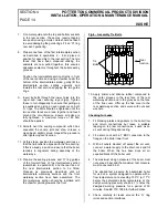
Fig.1 - General Data & Dimensions
(NOT TO SCALE - All measurements in millimetres)
Table 1 – Boiler Dimensions
No of Sections
6
7
8
9
10
11
12
13
14
15
“L”
mm
1255
1435
1615
1795
1975
2155
2335
2515
2695
2875
“D” (Diameter)
mm
250
350
“B” (Diameter) mm
970
1150
1330
1550
1690
1870
2050
2230
2410
2590
NOTE: Each boiler is supplied with 2 x 3”-4” extension turrets, 2 x 3” flanges, 1 x blank flange, 1 x 1” flange for
drain cock and 1 x flange for thermostat connections.
Table 2 - Combustion Chamber Data
No of Sections
6
7
8
9
10
11
12
13
14
15
Mean Diameter
mm
635
Cross Sectional Area
m²
0.343
Length mm
920
1100
1280
1460
1640
1820
2000
2180
2360
2540
Volume
m
3
0.291 0.349 0.407 0.465 0.522 0.581 0.639 0.697
0.754
0.811
Surface Area
m
2
2.15
2.51
2.86
3.22
3.58
3.94
4.3
4.65
5.01
5.38
Resistance
mm
38
55
73
57
71
67
73
57
100
Flue Gas Temperature
(Gross)
°C
180
Efficiency (Net)
%
(Gross)
%
90
82.2
Percentage CO
2
Oil
%
Gas %
12
9
Heat Release
kW/m²
249.3 250.6 244.1 253.7 259.5 259.9 262.3 262.2 254.3 265.6
D
1070
205
195
100
P
1405
690
373
200
830
210
70
1" BSP
Drain
Connection
Control
Panel
L
Special flue adapter
box available for 6-9
section boiler only
REAR
SIDE
For P dimension refer to burner data sheet
200
690
1050
B
Note: Base must not
protrude from rear of boiler.