background image

19

Manual: NGP-1000D-M1/M2/M3

10. 

On  the  second  cycle,  open  the  Nitrogen  Test  Port  Valve 

(Green Handle) located on the inside of the cabinet.

11. 

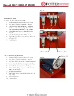
Turn on the Nitrogen Analyzer. See Figure 21. For more in

-

formation on the Nitrogen Analyzer


go to

 Nitrogen Analyzer 

Instructions

. See page 31.

12. 

Attach the Nitrogen Analyzer to the Nitrogen Test Port.

13.  The nitrogen purity level reading should climb to 98%+. If 

not go to 

Troubleshooting

. See page 21. 

14. 

Close the Nitrogen Test Port Valve (Green Handle) and dis

-

connect the Nitrogen Analyzer. Make sure to power off the 

Nitrogen Analyzer.

15. 

Do not leave the Nitrogen Test Port Valve (Green Valve) open 

for more than 2 minutes. The purity level may drop and fill 

times will be lengthened.

8. 

When the nitrogen storage tank pressure reaches 75±3

 PSI, 

the Nitrogen Solenoid light will turn OFF and the nitrogen 

membrane pressure will go to zero (0). See Figure 20.

9. 

Repeat  steps  5-8  a  second  time  to  ensure  nitrogen  storage 

tank fill up times are consistent.

16. 

Go to the end of the system where the NGP-SPV or INS-PV 

was installed. Open the ball valve to allow the units to begin 

purging. For the NGP-SPV, remove the plug covering the ex

-

haust orifice.

17. 

For INS-PV, press "Start Purge" button. For more informa

-

tion on the INS-PV or if an INS-RA is installed, refer to man

-

ual #5401532.

18. 

The system is now in operation.

Figure 20

Figure 21

Figure 22

Open Position

firealarmresources.com

Содержание NGP-1000D-M1

Страница 1: ...n Operation Service Manual Manual 5401549 Rev A 9 15 Potter Electric Signal Company LLC St Louis MO Customer Service 866 240 1870 Technical Support 866 956 1211 Fax 314 595 6999 www pottersignal com corrosion firealarmresources com ...

Страница 2: ...2 Manual NGP 1000D M1 M2 M3 firealarmresources com ...

Страница 3: ...ing Method 14 Nitrogen Purging Procedure 17 Nitrogen Control Module 20 Nitrogen Generator Alarms Troubleshooting 21 Nitrogen Generator Leak Check Method 23 Air Side Leak Check Method 24 Nitrogen Membrane Check 25 Sprinkler System Leak Check 26 NGP 1000D M1 M2 M3 Maintenance 27 Normal Operating Parameters of the NGP 1000D M1 M2 M3 29 Nitrogen Analyzer Instructions 30 Wiring Diagrams 33 Technical Sp...

Страница 4: ...s and regulations should be followed at all times Unpacking After unpacking unit carefully inspect all parts and equipment for any damage that may have occurred during transit Make sure to tighten fittings bolts etc before putting unit into service General Safety Information Important Read all of the safety information in this manual before operating this equipment Use of the equipment in a manner...

Страница 5: ...r is classified as non hazardous for transportation purposes and as non flammable for fire regulations This equipment is for indoor use only Do not operate outdoors Specific procedures must be developed for maintenance of the equipment on which the membrane separator is located Appropriate labels must be continuously displayed in all areas where personnel might be exposed to a nitrogen atmosphere ...

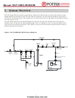
Страница 6: ... assembled package ready to be connected to a new or existing fire sprinkler system using a factory pre engineered air compressor These turn key systems include all air filtration equipment required to keep the generator operating at peak efficiency 2 System Overview Figure 1 NGP 1000D M1 M2 M3 System Diagram OPTIONAL ANALYZER QUICK CONNECT NITROGEN SOLENOID VALVE VALVE CHECK VALVE CHECK SEPARATOR...

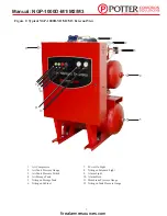
Страница 7: ... 3 4 5 1 Air Compressor 2 Air Tank Pressure Gauge 3 Air Tank Pressure Switch 4 Air Storage Tank 5 Nitrogen Storage Tank 6 Nitrogen Cabinet 7 Power On Light 8 Nitrogen Solenoid Light 9 Alarm Light 10 Alarm Horn 11 Membrane Pressure Gauge 12 Nitrogen Tank Pressure Gauge 7 8 firealarmresources com ...

Страница 8: ...3 Filter Drain Solenoid Test 4 Bypass Valve Yellow Handle 5 Bypass Alarm Switch 6 Nitrogen Tank Pressure Switch 7 Nitrogen Inlet Valve Blue Handle 8 5 Micron Filter 9 Coalescing Filter 10 Separator 11 Nitrogen Solenoid Valve 12 Air Tank Drain Solenoid Test 13 Nitrogen Test Port Valve Green Handle 14 Nitrogen Outlet Valve Blue Handle firealarmresources com ...

Страница 9: ... 1000D M3 2B THREE 9 2 208V 1119528 NGP 1000D M3 3B THREE 9 2 230V 1119529 NGP 1000D M3 4B THREE 4 6 460V Dimensions 62 x 44 x 33 H x W x D Dry clean and well ventilated Ambient temperatures above 50 F at all times Access to front for service Conveniently located near fire sprinkler system connections Conveniently located near drain The Potter Nitrogen Generator creates a 30 to 40 oxygen stream wh...

Страница 10: ...cessories Item Air Maintenance Device One per riser NGP SPV or INS PV One per riser Nitrogen Analyzer One per job Required items supplied by sprinkler contractor Item 4 anchor bolts fit holes on frame NPT piping from generator to system or greater Dedicated electrical circuit with electrical disconnect drain tubing if more than 10 ft are needed ball valve for isolation 4 Uncrating and Inspection A...

Страница 11: ...ined as air pressure from the drain valve may cause the tubing to be displaced from the drain 2 Install a ball valve at the nitrogen storage tank outlet connection The nitrogen storage tank comes with one female NPT connection located on each side Choose the one that is most convenient Plug the opposite tank connection See Figure 5 3 Close the ball valve 4 Install NPT piping from ball valve on the...

Страница 12: ...wiring instructions refer to the Wiring Diagram on page 34 Wiring location is in the nitrogen cabinet See Figure 8 7 Install NPT pipe or larger from the Air Maintenance Device AMD to the sprinkler system using standard accepted installation practices Additional system components may be required See Figure 7 NOTE AMD shown in closed position Figure 7 Figure 8 CLOSED CLOSED CLOSED firealarmresources...

Страница 13: ...enting the Nitrogen Purging Procedure For installation instructions refer to the Model NGP SPV Bulletin 5401520 or Model INS PV Manual 5401532 supplied with each purge valve NGP SPV Potter Purge Valve 1117984 INS PV Potter IntelliPurge Nitrogen Purge Valve 1119478 Purge Valves must be installed in a level horizontal position shown above firealarmresources com ...

Страница 14: ...ogen cabinet 5 Open the Bypass Valve Yellow Handle 6 Close the Nitrogen Inlet Valve Blue Handle and the Nitrogen Outlet Valve Blue Handle 7 Close the Nitrogen Test Port Valve Green Handle 8 Ensure the ball valve installed by contractor at the nitrogen storage tank outlet is closed Also ensure air storage tank petcock and nitrogen storage tank petcock are closed NOTE AMD shown in closed position Ni...

Страница 15: ...M2 M3 The air compressor will turn off at 105 3 PSI If the unit takes longer than the prescribed time or does not stop run ning when the unit reaches 105 3 PSI Go to the Trouble shooting section page 21 11 The compressor will shut off at 105 3 PSI air storage tank pressure This should not take longer than 7 minutes for the NGP 1000D M1 M2 M3 See Figure 13 12 Check all piping connections for leaks ...

Страница 16: ...s 19 As soon as sprinkler system supervisory pressure is reached put the sprinkler system back into service by placing the Air Maintenance Device in the maintenance position refer to the air maintenance device manual for proper operation See Figure 16 If there is more than one AMD on the system then close the others Fill one system at a time If there is more than one AMD on the system fill EACH sy...

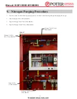
Страница 17: ... injecting nitrogen and purging the oxygen 2 Close the Bypass Valve Yellow Handle 3 Open the Nitrogen Inlet Valve Blue Handle 4 Open the Nitrogen Outlet Valve Blue Handle Figure 17 Nitrogen Outlet Valve Blue Handle Nitrogen Test Port Valve Green Handle Nitrogen Inlet Valve Blue Handle Bypass Valve Yellow Handle firealarmresources com ...

Страница 18: ... 14 minutes for the NGP 1000D M2 and 8 minutes for the NGP 1000D M3 NOTE The air compressor will cycle on and off during this process 5 Open the petcock on the nitrogen storage tank bottom tank and relieve the pressure until the Nitrogen Solenoid light turns ON See Figure 18 The Nitrogen Solenoid light should turn on at 60 3 PSI on the nitrogen tank pressure gauge Figure 18 Figure 19 Nitrogen Stor...

Страница 19: ...Test Port Valve Green Valve open for more than 2 minutes The purity level may drop and fill times will be lengthened 8 When the nitrogen storage tank pressure reaches 75 3 PSI the Nitrogen Solenoid light will turn OFF and the nitrogen membrane pressure will go to zero 0 See Figure 20 9 Repeat steps 5 8 a second time to ensure nitrogen storage tank fill up times are consistent 16 Go to the end of t...

Страница 20: ...row key to scroll through the log screens below To get out of the log press ALT then up arrow and press ALT again to get to main display PLC Operation Nitrogen Control Module Screen Nitrogen Solenoid Hours and Cycle Screen Alarm 1 and 2 Counts Screen Alarm 5 and 6 Counts Screen Alarm 7 Counts Screen Compressor Hours and Cycle Screen Alarm 3 and 4 Counts Screen Normal operation does not require any...

Страница 21: ...e Nitrogen Outlet Valve Blue Handle Refer to Nitrogen Purging Procedure on page 17 2 If the unit is filling multiple systems or being left intentionally in Bypass Mode mute the Alarm Horn by pressing the button on the inside of the cabinet on the back of the Alarm Horn Alarm 3 Compressor Overload Issue The control panel has tripped due to a motor overload Answer 1 Turn power OFF to the nitrogen ge...

Страница 22: ...is water in my drain hose Answer 1 Press the Filter Drain Solenoid Test Button on the inside of the cabinet to test if the drain is working 1 Ensure all the ball valves are in the correct position for Ni trogen Mode go to Nitrogen Purging Procedure See page 17 2 Adjust the needle valve on the inside of the cabinet to 98 nitrogen See Figure 24 NOTE Nitrogen storage tank needs to be at 60 3 PSI when...

Страница 23: ... the nitrogen generator The Power On light on the outside of the cabinet should turn green 10 Allow the pressure in the air storage tank and the nitrogen storage tank to rise The green Nitrogen Solenoid light should be ON 11 Once the air compressor and Nitrogen Solenoid light have both turned off record the pressure on the air storage tank and the nitrogen storage tank a This should typically take...

Страница 24: ...erator ON The Power On light should be green 7 Allow the pressure to build to 105 3 PSI Make note the time it takes to reach this pressure a This should typically take less than 5 minutes for the NGP 1000D M1 M2 M3 8 If the unit reaches 105 3 PSI and does not stop this could indicate a pressure switch issue Call Potter Technical Support at 1 866 956 1211 9 If the unit reaches 105 3 PSI and stops a...

Страница 25: ...n Outlet Valve Blue Handle 5 Exhaust the gas in the nitrogen storage tank by using the petcock on the bottom of the tank until the nitrogen storage pressure is 60 3 PSI and the Nitrogen Solenoid light turns ON 6 Quickly close the petcock 7 Record the time it takes for the Nitrogen Solenoid light to turn off a For the NGP 1000D M1 this should typically take 20 minutes b For the NGP 1000D M2 this sh...

Страница 26: ...or 1 5 PSI leak over 24 hours per NFPA 13 s new system leak rate unless specified otherwise To keep system in service the unit can run in Bypass Mode while arrangements are made to fix sprinkler system leaks Note the unit will alarm if left in Bypass Mode for longer than 1 hour This can be silenced by pressing the button on the back of the Alarm Horn A LED will light on the back of the Alarm Horn ...

Страница 27: ...on Coalescing Filters Annually Nitrogen Purity Analyzer Sensor Battery as Required Pressure Settings Inspected Quarterly Air Compressor Maintenance Schedule Weekly Drain condensate from receiver and traps Check for unusual noise or vibration Clean air filters only with non petroleum based products Clean all external parts of the compressor and motor Monthly Manually test safety relief valve Inspec...

Страница 28: ...er elements using filters provided in the replacement kit 7 Check for leaks Air Compressor Replacement 1 Isolate the nitrogen generator and relieve pressure 2 Disconnect the power to the nitrogen generator 3 Disconnect wires in junction box on the air compressor 4 Loosen union after flex hose on compressor discharge 5 Remove flex hose from compressor discharge 6 Remove bolts holding compressor to ...

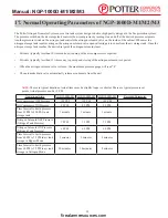
Страница 29: ...n solenoid valve is closed the membrane pressure gauge will read 0 The automatic drain valve automatically releases condensate from the unit 17 Normal Operating Parameters of NGP 1000D M1 M2 M3 Operational State NGP 1000D M1 NGP 1000D M2 NGP 1000D M3 Recorded Parameter Air Compressor OFF Pressure 105 PSI 105 PSI 105 PSI Air Compressor ON Pressure 85 PSI 85 PSI 85 PSI Time Interval to build pressur...

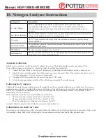
Страница 30: ...the analyzer by threading the barbed adapter onto the oxygen sensor 2 Attach the other end of the sample hose to the sample gas source and initiate flow of the sample to the unit at a rate of 1 10 liters per minute 2 liters per minute is recommended 3 Using the ON OFF key make sure the unit is in the power ON mode 4 Allow the nitrogen reading to stabilize This will take approximately 30 seconds or...

Страница 31: ...nt CAL Err Bat Battery voltage too low to recalibrate Replace batteries Changing the Batteries When the batteries need to be changed the device will indicate this in one of two ways The battery icon on the bottom of the display will begin to flash This icon will continue to flash until the batteries are changed The unit will continue to function normally for approx 200 hours If the device detects ...

Страница 32: ...e to orient the new sensor by aligning the red arrow on the sensor with the arrow in the back case A small tab is located on the back case that is designed to engage the sensor and prevent it from rotating within the case NOTE If the oxygen sensor is installed incorrectly the case will not come back together and the unit may be damaged when the screws are reinstalled Reconnect the oxygen sensor to...

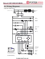
Страница 33: ...OMPRESSOR MOTOR AIR TANK DRAIN SOLENOID FILTER DRAIN SOLENOID DRAIN TEST BUTTON ALARM TERMINALS CUSTOMER CONNECTIONS 9 8 N O N O 11 12 NITROGEN SOLENOID LIGHT DRAIN TEST BUTTON 4 OVERLOAD 6 5 7 3 2 1 CONTACTOR OVERLOADS NITROGEN SOLENOID COMPRESSOR CONTACTOR CONTROL POWER LIGHT 95 96 A1 A2 14 13 COMPRESSOR AUX CONTACT F1 R C G SW 1 BYPASS VALVE SWITCH PS 2 60 75 PSI PS 1 85 100 PSI 115 208 230V 1 ...

Страница 34: ...Q3 Q2 Q1 10 COMPRESSOR MOTOR AIR TANK DRAIN SOLENOID FILTER DRAIN SOLENOID DRAIN TEST BUTTON ALARM TERMINALS CUSTOMER CONNECTIONS 9 8 N O N O 11 12 NITROGEN SOLENOID LIGHT DRAIN TEST BUTTON 4 OVERLOAD 6 5 7 3 2 1 CONTACTOR OVERLOADS NITROGEN SOLENOID COMPRESSOR CONTACTOR CONTROL POWER LIGHT 95 96 A1 A2 14 13 COMPRESSOR AUX CONTACT F2 F1 R C G PS 2 60 75 PSI PS 1 85 100 PSI 208 230 460V 3 PH 60 HZ ...

Страница 35: ...1 6A 230V 11A single phase and 208V 9 2A 230V 9 2A 460V 4 6A three phase Fire Sprinkler System Connection Female NPT Mounting Holes 4 Ø Max operating Pressure 105 PSI Temperature Range 50 F 10 C to 110 F 43 C Air Purity ISO Class 1 4 1 or better Free of water 38 F 3 C Dew Point compressor oil 0 008 PPM or 01 mg m3 hydrocarbons and particles 0 01 μm microns Size HxWxD 62 x 44 x 33 Weight 550 lbs Po...

Страница 36: ...3 8 43 3 4 PS 1 PRESSURE SWITCH WITH UNLOADER AIR TANK PRESSURE GAUGE OIL LESS AIR COMPRESSOR CHECK VALVE POWER ON LIGHT NITROGEN SOLENOID LIGHT ALARM LIGHT ALARM HORN MEMBRANE PRESSURE GAUGE NITROGEN TANK PRESSURE GAUGE 1 2 FNPT NITROGEN OUTLET CONNECTION 2 PLCS REVISIONS REV ENG CHG NO DESCRIPTION DATE BY CHK A RELEASED 7 15 NWD MJA D C B A CAD GENERATED DRAWING DO NOT MANUALLY UPDATE SCALE SIZE...

Страница 37: ...30 PS 1 PRESSURE SWITCH WITH UNLOADER OIL LESS AIR COMPRESSOR AIR TANK PRESSURE GAUGE CHECK VALVE POWER ON LIGHT NITROGEN SOLENOID LIGHT ALARM LIGHT ALARM HORN MEMBRANE PRESSURE GAUGE NITROGEN TANK PRESSURE GAUGE 1 2 FNPT NITROGEN OUTLET CONNECTION 2 PLCS REVISIONS REV ENG CHG NO DESCRIPTION DATE BY CHK A RELEASED 7 15 NWD MJA D C B A CAD GENERATED DRAWING DO NOT MANUALLY UPDATE SCALE SIZE DWG NO ...

Страница 38: ...PS 1 PRESSURE SWITCH WITH UNLOADER OIL LESS AIR COMPRESSOR AIR TANK PRESSURE GAUGE CHECK VALVE POWER ON LIGHT NITROGEN SOLENOID LIGHT ALARM LIGHT ALARM HORN MEMBRANE PRESSURE GAUGE NITROGEN TANK PRESSURE GAUGE 1 2 FNPT NITROGEN OUTLET CONNECTION 2 PLCS REVISIONS REV ENG CHG NO DESCRIPTION DATE BY CHK A RELEASED 7 15 NWD MJA D C B A CAD GENERATED DRAWING DO NOT MANUALLY UPDATE SCALE SIZE DWG NO D S...

Страница 39: ... the warranty are warranted for the remainder of the Warranty Period of the product upon which installed to the same extent as if such parts were original components DISCLAIMER THE FOREGOING WARRANTY IS EXCLUSIVE AND IT IS EXPRESSLY AGREED THAT EXCEPT AS TO TITLE THE COMPANY MAKES NO OTHER WARRANTIES EXPRESSED OR IMPLIED OR STATUTORY INCLUDING ANY IMPLIED WARRANTY OR MERCHANTABILITY THE REMEDY PRO...

Отзывы: