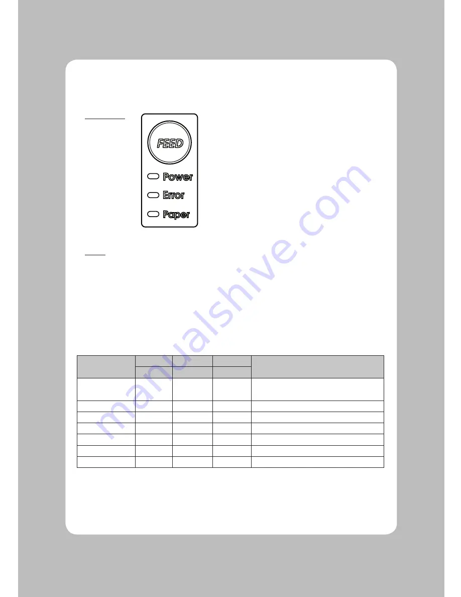
Posligne ODP-500 Скачать руководство пользователя страница 13

12

3-1. Control panel

You can control the basic paper feeding operations of the printer with the button on the control panel. 
The indicator lights let you to monitor the printer’s status.

Control Panel


Button

The button can be disabled by the ESC c 5 command.

Press the FEED button once to advance paper one line. You can also hold down the FEED button to 
feed paper continuously.

3-2. Error indicators

This section explains the different patterns signaled by the two LED indicators located on the top cover 
of the printer.

STATUS

PAPER

ERROR

POWER

REMARKS

RED

RED

GREEN

Power off

OFF

OFF

OFF

Normal power is not supplied to the 

printer

Power on

OFF

OFF

ON

Normal power is supplied to the printer

On line

OFF

OFF

ON

Normal error-free mode

Cover open

OFF

ON

ON

Close cover

Paper empty

OFF

ON

ON

Insert new paper roll

Paper near end

ON

OFF

ON

Paper is low

Test mode

OFF

OFF

ON

Ignored error led

3. Control panel and other functions

Содержание ODP-500

Страница 1: ...Receipt Printer User s Manual MODEL ODP 500 All specifications are subject to change without notice...

Страница 2: ......

Страница 3: ...rol panel and other functions 12 3 1 Control panel 12 3 2 Error Indicating 12 4 Self Test 13 5 Hexadecimal Dump 14 6 Specifications 15 6 1 General Specifications 15 6 2 Auto Cutter Specifications 17 6...

Страница 4: ...ITCH POWER CONNECTOR PERIPHERAL DRIVE CONNECTOR INTERFACE CONNECTOR INTERFACE CONNECTOR USB Open this cover to load or replace paper Features LED indicators to indicate printer status and switches to...

Страница 5: ...r printer box should include these items If any items are damaged or missing please contact your dealer for assistance The Printer User s Manual Roll Paper Adaptor Option Interface Cable option 2 Sett...

Страница 6: ...the printer and the computer are turned off INTERFACE CONNECTOR PERIPHERAL DRIVE CONNECTOR POWER CONNECTOR INTERFACE CONNECTOR USB For connection to a host computer For connection to a host computer...

Страница 7: ...er transmit data line 3 DATA Printer transmit data line 4 GND System Ground Serial Interface PIN SIGNAL I O DESCRIPTION 2 TxD Output Printer transmit data line RS 232C level 3 RxD Input Printer receiv...

Страница 8: ...13 SELECT Output Printer status for ON OFF line 14 AUTO FEED Input Paper auto feed signal 15 GROUND System ground 16 GROUND System ground 17 NC 18 LOGIC H 5V 19 30 GROUND System ground 31 INIT Input I...

Страница 9: ...11 modular connector The driver is capable of supplying a maximum current of 0 1A for 510ms or less when not printing PIN SIGNAL DESCRIPTION 1 Signal GND 2 Drawer kick out drive signal 1 Output 3 Dra...

Страница 10: ...lued to the core because the printer cannot detect the paper end correctly Turn off power switch 1 Make sure that the printer is not receiving data Otherwise data may be lost 2 Open the paper roll cov...

Страница 11: ...10 5 Note the correct direction that the paper comes off the roll 6 Pull out a small amount of paper as shown Then close the cover 7 Tear off the paper as shown...

Страница 12: ...this case repeat power on and off several times If the top cover is still stuck please follow the steps to release the paper jam 1 Make sure the printer is turned off 2 Take out cutter cover as shown...

Страница 13: ...continuously 3 2 Error indicators This section explains the different patterns signaled by the two LED indicators located on the top cover of the printer STATUS PAPER ERROR POWER REMARKS RED RED GREE...

Страница 14: ...olding down the FEED button turn on the printer using the switch on the front of the printer to begin the self test The Self Test prints the printer settings cuts the paper then pauses Error LED On Se...

Страница 15: ...follow these steps 1 Please run the self test While holding down the FEED button turn on the printer using the switch on the front of the printer to begin the self test 2 Please holding down FEED butt...

Страница 16: ...80 DPI X 180 DPI 4 Dot Pitch 0 142mm X 0 142mm 5 Printing Width Max 72mm 512 dots 6 Number of print columns Font A Font B 42 columns 56 columns 7 Roll paper Refer to chapter 2 for details on the recom...

Страница 17: ...16 8 Overall dimension...

Страница 18: ...3 Interface RS232 Serial Interface Centronics Parallel Interface IEEE1284 USB Interface Ethernet Interface 10Mbps Wi fi 802 11B 6 4 Electrical Characteristics 1 Input Voltage DC 24V 10 2 Current Cons...

Страница 19: ...ting Temperature 5 C to 40 C Humidity 10 to 90 RH without condensation 2 Transport Storage except paper Temperature 20 C to 60 C Humidity 10 to 90 RH without condensation 6 6 Reliability 1 MCBF 50 mil...

Страница 20: ...3 Set line spacing 19 ESC Select peripheral device 20 ESC Cancel user defined characters 21 ESC Initialize printer 22 ESC D Set horizontal tab positions 23 ESC E Turn emphasized mode on off 24 ESC G...

Страница 21: ...lect cut mode and cut paper 54 GS W Set printing area width 55 GS Set relative vertical print position in page mode 56 GS a Enable disable Automatic Status Back ASB 57 GS f Select font for HRI charact...

Страница 22: ...21...

Страница 23: ...22...

Страница 24: ...Rev 1 0...

Отзывы: