background image


15 

5.2


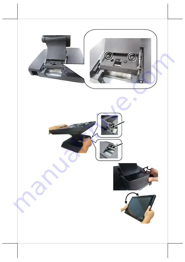
Remove the two screws from the base. 


5.3


Support the screen with one hand holding onto its bottom edge.  
Then, while pulling the lever backwards, move the display 
upwards or downwards until the lever is snapped into the upper 
hook to lower the screen as shown in the below figure. 


5.4


Push the cable cover back. 


5.5


Tilt the screen up or down to your 
desired angle. Please do not press on 
the LCD panel while setting up the 
tilt angle. 


Lever 

Upper 
hook 

Remove the two screws. 


Содержание XT-6015C

Страница 1: ...Terminal with base stand x1 60W power adaptor x1 Power cord x1 Screw for IO cable cover x2 User manual x1 Recovery or information CD x1 XT 6015C Fanless POS Terminal User Manual 16760905030 Ver C0 htt...

Страница 2: ...to the following two conditions 1 This device may not cause harmful interference and 2 this device must accept any interference received including interference that may cause undesired operation CE CL...

Страница 3: ...esult in an explosion or the leakage of flammable liquid or gas BATTERIE ATTENTION NOTES Jetez les piles usag es conform ment aux instructions Remplacement d une batterie avec un type incorrect qui pe...

Страница 4: ...on WiFi BT module through M 2 Interface Connection Cable RJ50 to DB9 serial port conversion cable Split cable for 2 cash drawer control Base GEN 8E base including poweredUSB board and supporting 60W 8...

Страница 5: ...7E Base Stand Bottom View of Terminal with GEN 7E Base Stand Neck Cover DDR4 Memory Cover LCD Touch Panel Power Indicator Base Stand Hinge for main unit Cable Exit Cable Cover Bottom Plate Rubber Cush...

Страница 6: ...inal with GEN 8E Base Stand Power Button Brightness Adjustment Button Brightness Adjustment Button USB 2 0 Port Locking Hook DDR4 Memory Cover LCD Touch Panel Power Indicator Base Stand Hinge for main...

Страница 7: ...n 7E 8E and allow you to determine an ideal position for your terminal by using its unique tilt adjustment mechanism As the below figures suggest both bases provide three standard positioning solution...

Страница 8: ...ting up the tilt angle XT 6015E with Gen 7E Base Please refer to the following instructions on how to switch among different positioning modes to find an ideal viewing angle for XT 6015C with Gen 7E b...

Страница 9: ...lever is snapped into the lower hook to raise the screen as shown in the below figure 3 3 With the screen facing toward you tilt the screen up or down to your desired angle Please do not press on the...

Страница 10: ...your terminal back to Flat Folded mode from Full Extended mode 4 1 Remove the cable cover from the base 4 2 Remove the two screws from the base 4 3 Tilt your screen in a horizontal position Remove the...

Страница 11: ...ding onto its bottom edge While pulling the lever backwards move the display downwards until the lever is lifted off the hook as shown in the figure 4 5 Push the cable cover back 4 6 Tilt the screen a...

Страница 12: ...NOT press on the LCD panel while setting up the tilt angle XT 6015C with Gen 8E Base Please refer to the following instructions on how to switch among different positioning modes to find an ideal view...

Страница 13: ...one hand holding onto its bottom edge Then while pulling the lever backwards move the display upwards until the lever is snapped into the lower hook to raise the screen as shown in the below figure 4...

Страница 14: ...32 14L screws 4 4 Push the cable cover back 5 Position the terminal in Low Profile mode 5 1 While keeping your terminal steady with your hand holding on to the base tilt your terminal down Then remove...

Страница 15: ...r backwards move the display upwards or downwards until the lever is snapped into the upper hook to lower the screen as shown in the below figure 5 4 Push the cable cover back 5 5 Tilt the screen up o...

Страница 16: ...onto the base tilt your screen up 6 2 Support the screen with one hand holding onto its bottom edge While pulling the lever backwards release the lever back to the point above the upper hook as shown...

Страница 17: ...acket to secure the power cord Connecting Power Cable Connector to the Terminal Before turning turn ON the terminal connect the power cable connector to the power jack of the terminal CAUTION On doing...

Страница 18: ...em Power Indicator There is a power LED indicator serving for several purposes located at the center of lower rim of LCD panel The relationship between the indicator status and other conditions is sum...

Страница 19: ...x RJ50 RJ 50 to DB9 cable Optional RS 232 signal only Jumper selectable 5V 12V support on all COM ports CR Port 1 port available for controlling 2 CR USB Port Standard 4 ports on the I O plate 2 x USB...

Страница 20: ...20 MEMO...

Отзывы: