POSIFLEX SA-304 Скачать руководство пользователя страница 2


Hardware Installation 

During Installation of the SA-304/305 and SL-305, do NOT power ON your 
terminal and monitor. 

Installation of SA-304 onto the 14” XT Series Terminals  
(except XT-2614E) 

Start to install SA-304 onto according to the following steps. 
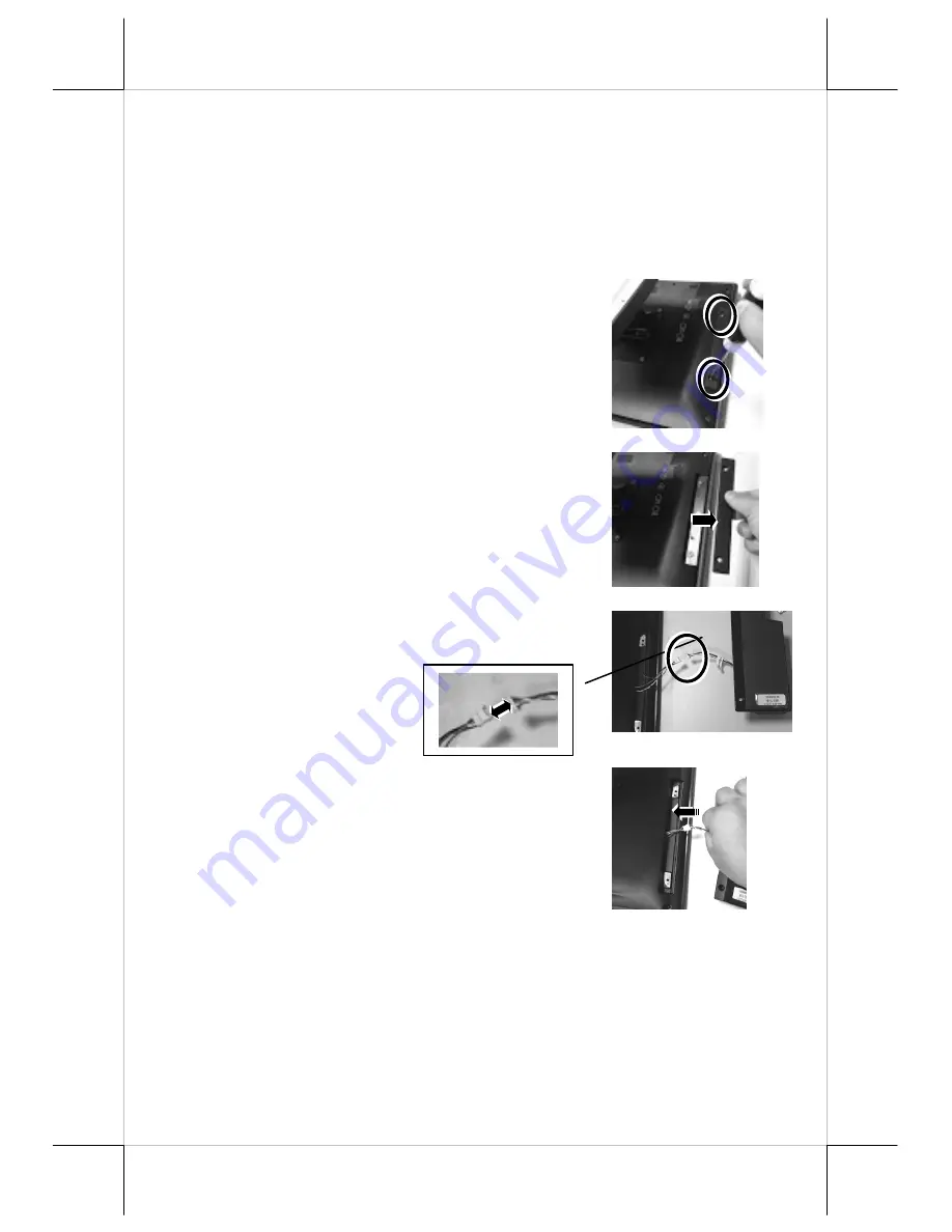
1.


Loosen and remove the two fixing screws 
from the side mount cover on the back of 
the right side of the terminal. 


2.


Remove the side mount cover from the back 
of the right side of the terminal. 


3.


Insert the USB IO cable of the SA-304 into 
the cable connector of the main board. 


4.


Determine whether the cable is well 
connected to the cable connector. Then, 
push the cable into a space between the rear 
cover and the mainboard. 


Содержание SA-304

Страница 1: ...on CD shipped with SL 305 only RFID Mifare Card Optional RFID Ring Tag Optional Views of the Magnetic Stripe Reader Front View Right Side View SA 304 305_SL 305 Fanfree LCD Touch Terminal Quick Installation Guide USB I O Cable 3 track Magnetic Stripe Reader RFID Mifare Card Reader Optional Fingerprint Sensor with Status LED Indicator Optional 18600901020 Ver A0 http www posiflex com ...

Страница 2: ...ollowing steps 1 Loosen and remove the two fixing screws from the side mount cover on the back of the right side of the terminal 2 Remove the side mount cover from the back of the right side of the terminal 3 Insert the USB IO cable of the SA 304 into the cable connector of the main board 4 Determine whether the cable is well connected to the cable connector Then push the cable into a space betwee...

Страница 3: ...s shipped with the package 7 The installation of SA 304 onto the terminal is completed as shown in the right figure Installation of SA 305 onto the 15 17 XT Series Terminals Start to install SA 305 onto the terminal according to the following steps 1 Loosen and remove the two fixing screws from the side mount cover on the back of the right side of the terminal ...

Страница 4: ...ert the USB IO cable of the SA 305 into the cable connector of the main board If the SA 305 is provided with two USB IO cables for two types of readers you can connect the IO cables to the two cable connector of the main board 5 Determine that the USB IO cable is securely connected to the cable connector of the main board Cover A Cover B ...

Страница 5: ...in the right figure 8 Align the two screw holes of the SA 305 MSR cover with the two screw holes on the terminal 9 Fix the SA 305 MSR onto the terminal by locking the two long screws shipped with the package 10 The installation of SA 305 onto the terminal is completed as shown in the right figure ...

Страница 6: ...3 Insert the USB IO cable of the SL 305 into the cable connector of the main board 4 Determine whether the USB IO cable of SL 305 is well connected to the cable connector of the main board Then push the connected cable into a space between the rear cover and the mainboard 5 Align the two screw holes of the SL 305 MSR cover with the two fixing holes of the LM TM 3X15 and then fix the SL 305 MSR ont...

Страница 7: ...of which the OS is pre loaded you can find the drivers and utilities for SA 304 305 from the Drivers folder in the Local Disk C and then double click the executing file to install or directly open For SL 305 working with the TM LM 3X15 series monitor insert the Peripheral Information CD shipped with the SL 305 package into your CD ROM for driver and utility installation Installing the Posiflex USB...

Страница 8: ...USB device to appear as an additional COM port available to the PC Application software can access the USB device in the same way as it would access a standard COM port 1 Left click Start Programs Posiflex Tools Posiflex USB MSR Manager 2 The Posiflex USB MSR Manager appears as shown in the right figure Then tick off on virtual COM port interface 3 Left click the Setup logo at the row of USB MSR V...

Страница 9: ...3X0 Setup Tools to install the RFID setup tools 2 Then follow the step by step instructive messages to complete the tool installation 3 After completion of the tool installation restart your terminal 4 Left click the RFID setup tools icon and then the tool appears Operation of the Magnetic Stripe Reader After installing the drivers and tools you can start to operate the SA 304 305 and SL 305 model...

Страница 10: ...allow the fingerprinter sensor to read your thumb fingerprint Checking the LED status Standby status solid blue Reading Status solid blue and solid red The red LED will be off after around 2 seconds To get the detailed information on SA 304 305 and SL 305 please download the technical manual of this model from Posiflex Global Website http www posiflex com en global Download download Reading Area ...

Отзывы: