background image


3.


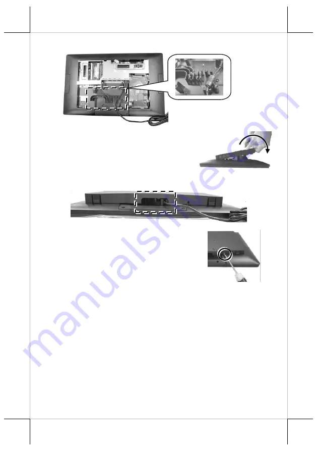
Neatly


arrange the cables along the cable slots. 


4.


Place back the sytem back cover. Make sure it 
is well locked into place with a click sound. 


5.


Make sure the cable could be pulled out of the cable exit from the bottom 
of the base.


6.


Locate the dedicated back cover screw from the 
packing box. Then, please insert the screw into 
the screw hole indicated in the figure, and secure 
it. 


Installing Optional Upgrade Kits and Peripherals 

RT-2015E/2016E is an expandable model which allows you to upgrade its own 
capacity by additionally installing multiple peripheral devices, such as 
magnetic stripe reader (MSR), fingerprint or iButton sensors, and 2

nd

 POS 

monitor, according to your preference. The following will give you brief 
instructions on how to expand on your current POS system with these optional 
upgrade kits. Before proceeding with the installation of peripherals, please 
make sure the POS system is completely shut down to prevent damage. 


Содержание RT-2015E

Страница 1: ...x1 User manual x1 Screw for back cover x1 Views of RT 2015E 2016E Front View 15 RT 2015E 15 6 RT 2016E Rear View RT 2015E 2016E Fanless Touch POS Terminal User Manual P Cap Touch Panel LED indicator L...

Страница 2: ...2 Bottom View Right Side View Left Side View Release Lever for System Back Cover Brightness Adjustment Button Power Button Brightness Adjustment Button Rubber Shield for USB2 0 Port Screw Hole...

Страница 3: ...cover hold down the release levers at the bottom of the system back cover and then pulling the cover outwards 2 Connect the connector of the power adapter to the DC IN power jack If necessary properl...

Страница 4: ...nd secure it Installing Optional Upgrade Kits and Peripherals RT 2015E 2016E is an expandable model which allows you to upgrade its own capacity by additionally installing multiple peripheral devices...

Страница 5: ...m power ON Powering ON OFF RT 2015E 2016E Power ON RT 2015E 2016E Press down the power button to power on the POS Power OFF RT 2015E 2016E In most cases press the power button of the POS to power the...

Страница 6: ...to recover your system without the help of system integrators Please be advised to contact your service center for further assistance with system recovery Operation Environment To prevent RT 2015E 201...

Страница 7: ...USB Port External Port 1 3 1 x USB 3 0 on I O plate 2 x USB2 0 1 on I O plate 1 on side edge 2 1 x 24V PoweredUSB port PoweredUSB Port 1 x 24V PoweredUSB port LAN Port 1 x 10 100 1000 Mb on I O plate...

Страница 8: ...Sensor 2D scanner attachment for RT series LM TM 4010DP 9 7 2nd display for RT series terminal LM TM 4011DP 10 1 2nd display for RT series terminal LM TM 4015DP 15 2nd display for RT series terminal...

Страница 9: ...e protection against interference when operated in a commercial environment Operation of this equipment in a residential area is likely to cause interference in which case the user at his own expense...

Страница 10: ...10 MEMO...

Страница 11: ...11 MEMO...

Страница 12: ...12 MEMO...

Отзывы: